HYTROL ProSort 100 Elite Скачать руководство пользователя страница 8

that the packages are truly spaced properly. Attempting to sort packages with too 
little gap between them can cause jams. 
Note: The minimum gap necessary for sorting a package is a function of the width 
of the package. The charts below should be used in checking for proper gap.

* W = Maximum Package Width
Note: When sorting to both 
sides, the minimum gap from the 
above charts must be increased 
by 3 in.

Jam/Confirmation Photo-eye

—Photo-eyes mounted on each take-away spur of 

the sorter, as close to the sorter as possible. These eyes perform two functions:
1. Detect a product jam at the sorter “exit point.” If a package blocks this photo-eye 
for a longer time than it would take for the package to travel past the photo-eye 
normally, this indicated that the package is jammed. The sorter should be stopped 
and the jam cleared before restarting the sorter.
2. Divert confirmation. If a divert signal is given to a particular divert point, and no 
package is detected by the associated jam/confirmation photo-eye, an error has 
occurred. The sorter should be stopped and the error found and corrected before 
restarting the sorter.

Full  Line Photo-eye

—Photo-eyes mounted on each divert lane from the sorter, 

near the infeed end of that lane. These eyes are used to signal the system controls 
that a particular divert lane is full. The controls should then send any further 
packages assigned to that lane to the recirculation line until the full line photo-eye 
on that lane no longer indicates the full condition.

Recommended Controls Procedures 

The following are recommendations to assist in the design and installation of 
system controls that are interfacing with ProSort sorters.
• Do not place 24VDC control wires in the same wireway with AC power wires, 
especially if the AC power exceeds 240 volts. “Noise” produced in the control wires 
by the power wires may produce undesirable effects.
• Do not use optional “standard prox output” of the smart prox as a substitute for 
an encoder. The five inch spacing between divert shoes does not provide enough 
tracking resolution to accurately sort packages.
• Do not use manual override operator of the solenoid air valve to operate a divert 
switch while the sorter is running. Doing so bypasses the switch timing controls and 
may cause switch damage or a sorter crash.
• Do treat the tripping of any safety switch, motor overload, or low air pressure 
signal as an emergency stop. Inspect the safety switch and other parts of the 
sorter to be sure everything is in good working order before starting or restarting 
the sorter.

• Pneumatic Divert 

Switch Checklist

After all ProSort sections are installed 
and aligned, each divert switch should be 
checked for proper operations as follows:
1. Before air pressure is supplied to the 
divert switch solenoid air valve, manually 
pivot the switch back and forth between 
the non-divert and divert position 
checking for a free and smooth pivoting 
movement. Determine and remedy the 
cause of any switch binding. For proper switch alignment see figures 8C & 8D. 
If switch adjustment is necessary, loosen the jam nut on the cylinder rod. Screw 
cylinder rod into or out of rod end to adjust the switch and retighten jam nut.

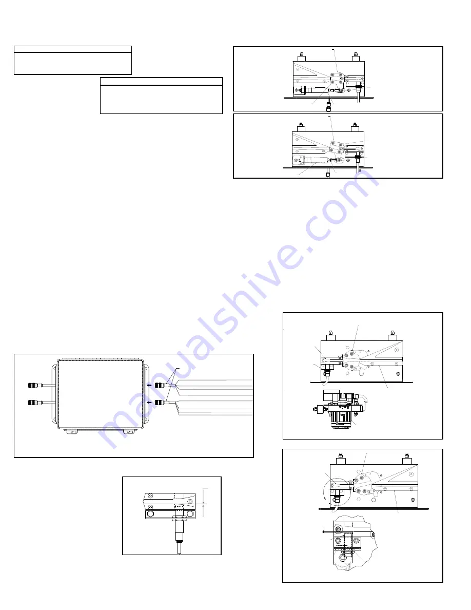
2. Turn air pressure on and verify that each divert switch is in, or moves to, the 
home (non-divert) position (Figure 8C).
3. Check to insure that the smart prox is set properly. The face of the prox should 
be set just out of the shoe pin guide path in the switch guide (Figure 8B)

•Electric Divert Switch Checklist

NOTE: All electric divert servo motors are paired with the associated drives at the 
factory. Connecting motors to the wrong drive may have an adverse effect on the 
divert operation and could result in physical damage to the sorter. Always connect 
the drives to the factory paired motors to prevent damage.
1. Before running the sorter, apply power to the electric switch system and verify 
that the diverts are fully in either the home or diverted position. Divert function was 
tested at the factory to ensure proper operation. If the diverts are in the diverted 
position, they can be returned to the home position, Figure 8E by removing the 
enable signal to the Smart Prox and then flagging the Smart Prox to trigger a 
move operation.
2. Each time diverts are powered on, the diverter will move slowly until it finds the 
home position. 
3. Ensure that the “All Systems Go” signal is on before running the sorter.
4. Check to ensure that the Smart Prox is set properly. The face of the prox should 
be set just out of the shoe pin guide path in the switch guide (Figure 8F). 

SWITCH BLOCK

(INTERRUPTOR DE 

BLOQUEO)

ROD END

(EXTREMO DEL EJE)

NON-DIVERT POSITION

(POSICION DESVIADORA)

AIR CYLINDER EXTENDER

(EXTREMO DEL EJE)

SWITCH BLOCK

(INTERRUPTOR DE 

BLOQUEO)

ROD END

(EXTREMO DEL EJE)

DIVERT POSITION

(POSICION DESVIADORA)

AIR RETRACTED

(EXTREMO DEL EJE)

JAM NUT

(CONTRA TUERCA)

FIGURE 8D

* BROKEN PROX OUTPUT IS ONLY ACTIVE WHEN SORTER RUN INPUT IS ACTIVE.

BROWN/

CAFÉ 

   NOT USED

BLACK/

NEGRO

   OUPUT (24V=OK, 0V=MISSING BEARING DETECTED) 


SALIDA (24 V = CORRECTO, 0 V = COJINETE FALTANTE DETECTADO)

BLUE/

AZUL

         COMMON/

COMÚN

WHITE/

BLANCO 

 BROKEN PROX ERROR  (24=OK, 0V=ERROR)/


             ERROR DE SENSOR DE PROXIMIDAD DAÑADO (24 = CORRECTO, 0 V = ERROR)

BROWN

/

CAFÉ

     POWER (+24VDC)/

ENERGÍA (+24 V CC)

BLACK/

NEGRO

   RESET ERROR INPUT/

ENTRADA DE ERROR DE RESTABLECIMIENTO

BLUE

/

AZUL


COMMON/

COMÚN

WHITE

/

BLANCO

   SORTER RUNNING INPUT (SORTER UP TO SPEED)


              ENTRADA DE CLASIFICADOR EN FUNCIONAMIENTO 


              (CLASIFICADOR A VELOCIDAD NORMAL)

941.423003

OUTPUT

INPUT

TO PROX 2

TO PROX 1

(HACIA SENSOR DE 
PROXIMIDAD 1)

(HACIA SENSOR DE 
PROXIMIDAD 2)

(SALIDA)

(ENTRADA)

(LA SALIDA DE SENSOR DE PROXIMIDAD DAÑADO SOLO SE ACTIVA CUANDO LA 
ENTRADA DE FUNCIONAMIENTO DEL CLASIFICADOR ESTÁ ACTIVA.)

FIGURE 8A

FIGURE 8C

1/32"

FIGURE 8B

V

V

NON-DIVERT POSITION

SERVO MOTOR

DIVERT BLOCK

PROX SWITCH


SWITCH GUIDE

NON-DIVERT POSITION

(POSICIÓN SIN DESVIACIÓN)

(GUÍA DEL 
INTERRUPTOR)

(INTERRUPTOR 
DE PROXIMIDAD)

(BLOQUE DE DESVIACIÓN)

(POSICIÓN SIN DESVIACIÓN)

(SERVOMOTOR)

FIGURE 8E

U

DIVERT POSITION

DIVERT BLOCK

SWITCH GUIDE

SWITCH BLOCK

PROX SWTICH 

DETAIL U

SCALE 1.50 : 1

1/32

(BLOQUE DEL 
INTERRUPTOR)

(GUÍA DEL 
INTERRUPTOR)

(INTERRUPTOR 
DE PROXIMIDAD)

(BLOQUE DE 
DESVIACIÓN)

(POSICIÓN DE 
DESVIACIÓN)

(DETALLE U)

(ESCALA 1.50: 1)

FIGURE 8F

ProSort 121 (22° Diverts)

  0” < W ²   6” 

Minimum gap =   6”

  6” < W ² 18” 

Minimum gap =   9”

18” < W ² 30” 

Minimum gap = 12”

ProSort 131 (30° Diverts)

  0” < W ²   6” 

Minimum gap =   6”

  6” < W ² 12” 

Minimum gap =   9”

12” < W ² 18” 

Minimum gap = 12”

18” < W ² 24” 

Minimum gap = 15”

8

Содержание ProSort 100 Elite

Страница 1: ...aci n sobre Seguridad y Lista de Refacciones LAS REFACCIONES RECOMENDADAS SE RESALTAN EN GRIS IMPORTANT DO NOT DESTROY IMPORTANTE NO DESTRUIR PRESS OPTIMIZED FOR THE ENVIRONMENT IMPRESI N OPTIMIZADA P...

Страница 2: ...2 Parts Drawings Catenary Divert Drive Section 32 Dual Divert Divert Return 33 Dual Divert Return Switch Tail 34 Induction Unit 35 ProSort 122 Parts List 36 37 Spanish Version 38 INTRODUCTION This man...

Страница 3: ...ch incorporates within its supporting structure platforms or control stations specifically designed for carrying personnel Under no circumstances shall any person ride on any element of a vertical con...

Страница 4: ...Install carrying chains per instructions on Page 8 9 17 Install chain oiler at infeed and connect to oil lines as shown in Figure 5B Refer to the Lubrication section page 6 for type of oil required A...

Страница 5: ...ergency stop devices shall be installed so that they cannot be overridden from other locations D Inactive and unused actuators controllers and wiring should be removed from control stations and panel...

Страница 6: ...e movement of the switch mechanism is not timed to occur only when no shoe is present in the switch the guide pin of the shoe may collide with the point of the divert block resulting in damage to the...

Страница 7: ...provided with the sorter for wiring instructions ENCODER An encoder is included with the sorter to provide a pulse signal to be used for product tracking The encoder provides a square wave pulse sign...

Страница 8: ...Screw cylinder rod into or out of rod end to adjust the switch and retighten jam nut 2 Turn air pressure on and verify that each divert switch is in or moves to the home non divert position Figure 8C...

Страница 9: ...into the conveyor during installation Also inspect divert shoes to make sure all of them have been installed on the correct centers If chains are ever shortened it must be in increments of three inche...

Страница 10: ...e way Remove the 5 wire M12 cable and black power cable from the splitter cable 4 By reaching through the uncovered hole in the side channel remove the two nuts at the back side of the switch assembly...

Страница 11: ...tight on slats 2 Slats dirty 3 Slats bent 4 Switch mis adjusted 1 Replace slat shoe assembly 2 Clean surface Refer to Preventive Maintenance Details 3 Replace slat shoe assembly 4 Refer to Divert Swi...

Страница 12: ...in PLST 1 2 in PLST 1 2 in PLST Plug In Reducer 3 8 in PLST 1 2 in Push In M18 Internal Tooth Lockwasher ZP 35 36 37 38 39 923 0172 923 0173 043 101 MP 002541 Positioning Stud 5 16 in 18 X 2 1 2 in LG...

Страница 13: ...M Hex Locknut Nylon Insert Rubber Vibration Mount 1 1 2 in DIA Switch Guide ProSort 100 21 22 23 24 25 MP 002616 092 18466 092 184907 098 150 923 0220 Switch Bearing Teknic Nylon 6 6 PRO 400 Switch Bl...

Страница 14: ...8 124 36 33 38 124 46 44 33 35 44 39 33 24 13 26 21 20 16 23 6 8 27 22 7 2 10 17 28 4 125 31 37 40 24 11 127 126 33 11 11 45 45 39 40 39 40 52 55 43 53 51 12 13 3 5 137 137 Model ProSort 131 Elite Par...

Страница 15: ...6 132 131 65 75 66 137 137 Model ProSort 131 Elite Parts Drawing Dibujo de piezas del modelo ProSort 131 Elite Intermediate Divert and Tail Section Secci n de retorno y desviaci n intermedia NOTE Plac...

Страница 16: ...6 80 103104 109 110 81 113 82 83 Model ProSort 131 Elite Parts Drawing Dibujo de piezas del modelo ProSort 131 Elite Induction Unit Unidad de inducci n Ref No Part No Description 1 2 3 4 5 P 01898 P 0...

Страница 17: ...OAW DIVERT ANGLE PS100E Y BLOCK SUPPORT PLATE 30D WEARSTRIP TIE STRAP SWITCH ASSY LH 30 DEG 17 18 19 20 SA 066648 WA 040365 WA 040366 PT 174779 SWITCH ASSY RH 30 DEG BED SPACER WELD specify OAW SWITCH...

Страница 18: ...eeds 59 60 61 62 63 095 155 927 0360 B 18450 MP 002345 PT 098832 256 Shank Brush for Chain Lubricator Bearing 4 Bolt 1 15 16 bore Oiler Mount Bracket Chain Guide Wearstrip Tail Belt Brush 32 lg Ref No...

Страница 19: ...71 8 ft 3 in Long 8 ft 6 in Long 8 ft 9 in Long 9 ft Long 9 ft 3 in Long 123 124 B 23572 B 23573 B 02633 B 23581 069 7501 9 ft 6 in Long 9 ft 9 in Long 10 ft Long Gussett Angle LH or RH Bearing Profil...

Страница 20: ...32 47 29 30 26 21 20 16 23 8 6 24 13 40 39 33 24 11 44 22 7 2 10 17 28 4 125 31 37 27 11 45 126 127 46 56 50 42 49 25 35 52 43 18 55 53 51 12 13 3 5 137 137 Model ProSort 121 Elite Parts Drawing Dibu...

Страница 21: ...31 135 75 65 66 82 83 137 137 Model ProSort 121 Elite Parts Drawing Dibujo de piezas del modelo ProSort 121 Elite Intermediate Divert and Tail Section Secci n de retorno y desviaci n intermedia NOTE P...

Страница 22: ...120 119 100 85 86 94 97 79 89 96 92 84 108 88 90 85 86 93 117 95 114 115 87 107 91 78 111 79 95 101 102 99 107 105 106 80 103104 109 110 81 113 112 Model ProSort 121 Elite Parts Drawing Dibujo de piez...

Страница 23: ...scription 1 2 3 4 5 092 1782 092 1792 MP 002356 P 01898 P 01899 Y BLOCK LH 22 DEG PROSORT 100E Y BLOCK RH 22 DEG PROSORT 100E UHMW WEARSTRIP J LEG specify length CHAIN GUIDE WEARSTRIP TOP specify leng...

Страница 24: ...Ref No Part No Description 59 60 61 62 63 095 155 927 0360 B 18450 MP 002345 PT 098832 256 Shank Brush for Chain Lubricator Bearing 4 Bolt 1 15 16 bore Oiler Mount Bracket Chain Guide Wearstrip Tail...

Страница 25: ...23569 B 23570 B 21607 B 23571 8 ft 3 in Long 8 ft 6 in Long 8 ft 9 in Long 9 ft Long 9 ft 3 in Long 123 124 B 23572 B 23573 B 02633 B 23581 069 7501 9 ft 6 in Long 9 ft 9 in Long 10 ft Long Gussett An...

Страница 26: ...4 33 49 40 32 11 26 8 3 5 4 2 134 39 28 21 47 37 50 25 30 31 55 46 34 48 18 12 13 15 25 148 1 19 16 9 35 36 38 133 146 146 Model ProSort 132 Elite Parts Drawing Dibujo de piezas del modelo ProSort 132...

Страница 27: ...45 52 24 54 51 44 42 35 40 32 54 51 44 42 35 32 40 146 Model ProSort 132 Elite Parts Drawing Dibujo de piezas del modelo ProSort 132 Elite Dual Divert and Divert Return Desviaci n doble y retorno de d...

Страница 28: ...51 52 32 40 40 33 49 53 11 54 35 42 44 35 43 45 137 138 139 64 54 70 71 77 75 21 1 87 140 144 53 78 88 72 69 8 6 74 83 84 86 81 79 80 73 82 36 38 41 76 146 146 Model ProSort 132 Elite Parts Drawing Di...

Страница 29: ...13 114 119 111 92 105 120 117 109 106 124 131 125 105 123 122 112 126 127 129 124 128 129 130 132 108 107 96 97 118 89 110 99 90 98 104 100 96 97 103 96 97 100 95 102 Model ProSort 132 Elite Parts Dra...

Страница 30: ...30 LH or RH Sweep Block 30 Pin Guide Block Plate Pin Guide Ref No Part No Description 61 62 63 64 65 092 17855 092 17955 Y Block RH 30 Return Y Block LH 30 Return Chain Guide Wearstrip Bottom Y Block...

Страница 31: ...23309 B 23310 B 05494 B 23311 B 23312 5 ft 6 in Long 5 ft 9 in Long 6 ft Long 6 ft 3 in Long 6 ft 6 in Long B 23313 B 21606 B 23314 B 12082 B 23315 6 ft 9 in Long 7 ft Long 7 ft 3 in Long 7 ft 6 in L...

Страница 32: ...145 15 25 48 22 23 8 20 3 6 26 7 2 27 10 17 24 32 35 43 45 24 40 49 51 54 134 52 54 35 33 42 44 40 32 11 5 4 36 38 50 29 53 146 146 Model ProSort 122 Elite Parts Drawing Dibujo de piezas del modelo Pr...

Страница 33: ...7 68 35 65 66 60 59 64 58 61 62 DUAL DIVERT DUAL DIVERT RETURN 146 146 Model ProSort 122 Elite Parts Drawing Dibujo de piezas del modelo ProSort 122 Elite Dual Divert and Divert Return Desviaci n dobl...

Страница 34: ...4 6 8 83 84 72 54 52 35 42 44 33 36 24 38 41 32 40 DUAL DIVERT RETURN SWITCH BOTTOM VIEW SCALE NONE 78 88 87 140 144 24 54 51 24 49 35 43 45 32 40 53 146 146 85 73 82 Model ProSort 122 Elite Parts Dra...

Страница 35: ...115 116 131 123 105 125 131 91 92 93 94 113 114 119 126 127 128 124 128 129 130 132 108 107 96 97 118 89 110 99 90 103 97 100 96 98 95 96 97 104 102 100 122 112 Model ProSort 122 Elite Parts Drawing...

Страница 36: ...ription 66 67 Wearstrip Tie Strap Side Angle Dual Divert Section 81 inch long for 31 OAW 22 LH or RH 96 inch long for 37 OAW 22 LH or RH 111 inch long for 43 OAW 22 LH or RH 68 69 70 71 SA 073869 MP 0...

Страница 37: ...569 B 23570 B 21607 8 ft Long 8 ft 3 in Long 8 ft 6 in Long 8 ft 9 in Long 9 ft Long 132 B 23571 B 23572 B 23573 B 02633 B 23581 9 ft 3 in Long 9 ft 6 in Long 9 ft 9 in Long 10 ft Long Gussett Angle L...

Страница 38: ...ade todo el equipo al rea de instalaci n 4 Remueva todos los empaques y verifique si hay partes adicionales que puedan estar sujetas al equipo Aseg rese de que estas partes u otras partes ajenas al eq...

Страница 39: ...n de transportador Figura 39A Posicione las secciones en esta secuencia cerca del rea de instalaci n Montaje 1 Marque con tiza una l nea en el suelo para ubicar el centro del transportador 2 Una los...

Страница 40: ...PRESION AJUSTADO A 48 PSI FIGURA 40D 3 8 LINE LINEA DE 3 8 1 2 to 3 8 REDUCER REDUCTOR DE 1 2 A 3 8 1 2 TEE TE DE 1 2 1 2 MAIN LINE LINEA PRINCIPAL DE 1 2 3 8 FEMALE TO 3 8 MALE QUICK CONNECT FITTING...

Страница 41: ...ligro B Paros de Emergencia y Reinicio Los controles del transportador deber n estar dispuestos de tal manera que en caso de un paro de emergencia se requiera un inicio o arranque manual en la ubicaci...

Страница 42: ...dor para mover y mantener el interruptor ya sea en posici n standard o en desviar La v lvula est especialmente dise ada para una operaci n de alta velocidad necesaria para un tiempo exacto de desviaci...

Страница 43: ...iento defectuoso La entrada de clasificador en funcionamiento SORTER RUNNING INPUT debe permanecer energizada para que la salida de error de sensor de proximidad da ado BROKEN PROX ERROR OUTPUT se ene...

Страница 44: ...ustar el interruptor y apriete nuebamente la contratuerca 2 Accione la presi n de aire y verifique que cada interruptor desviador est o se mueva a la posici n est ndard no desviar Fig 44C 3 Revise que...

Страница 45: ...ransportador durante la instalaci n Tambi n asegurese de que todos los zapatos desviadores hayan sido instalados en los centros correctos Si las cadenas se acortan debe ser en incrementos de tres pulg...

Страница 46: ...siga los pasos siguientes 1 Desconecte toda fuente de alimentaci n el ctrica que vaya hacia el tablero conectado al desviador que necesita quitarse Esto incluye apagar el interruptor al frente del ta...

Страница 47: ...los tubos doblados 2 Limpie la superficie Refi rase al mantenimiento predentivo 3 Reemplace el tubo doblado 4 Dir jase a la Revisi n del Interruptor Desviador p gina 44 Interruptor desviador no est o...

Страница 48: ...rimestral Carrying Chains Check lubrication Chains will appear moist when properly lubricated Slat Shoe Assemblies Check physical condition of slats and shoes Replace any damaged slat shoe assemblies...

Отзывы: