4
SIDE CHANNEL
(CANAL LATERAL)
A1
A2
B2
B1
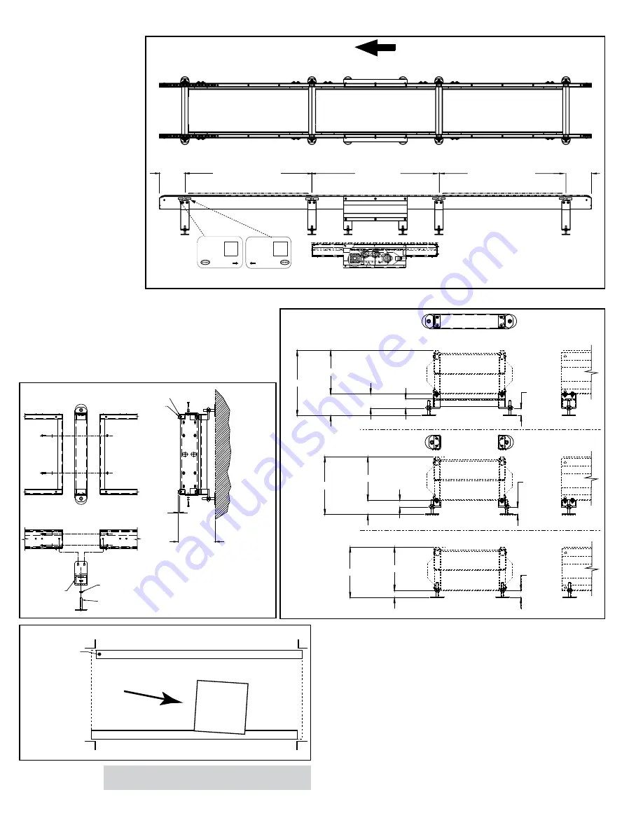
PREFERRED FLOW
(FLUJO PREFERIDO)
12" OPEN TAIL
(EXTREMO ABIERTO 12")
INTERMEDIATE MODULE
(MODULO INTERMEDIO)
DRIVE MODULE
(MODULO MOTRIZ)
INTERMEDIATE MODULE
(MODULO INTERMEDIO)
12" OPEN TAIL
(EXTREMO ABIERTO 12")
FIGURE 4A
“MATCH-MARK” NUMBERS
(NÚMEROS DE “MARCA DE REFERENCIA”)
FO:
MARK:
TOOL BOX
QR
CODE
H
Y
T
R
O
L
C
O
D
E
MODEL
A
FO:
MARK:
TOOL BOX
QR
CODE
H
Y
T
R
O
L
C
O
D
E
MODEL
A
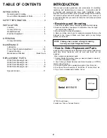
WEARSTRIP
CHAIN
1/2
TOP OF CHAIN
(TOPE DE CADENA)
SUPPORT
WELDMENT
5/8-11 HEX JAM NUT
FOOT PAD
(GUIAS DE CADENA)
(CADENA)
(CONTRATUERCA HEX 5/8-11)
(PIE DE SOPORTE)
(SOPORTE)
DCDS–04 THRU –10
DCDS–03
DCDS–02
17" - 31"
12"
5" - 19"
4" - 16"
2 5/8"
1" MIN
3" MAX
1" MIN
3" MAX
1" MIN
3" MAX
15" - 17"
12"
12"
3" - 5"
2"
13" - 15"
1" - 3"
TOP OF CHAIN
(TOPE DE CADENA)
TOP OF CHAIN
(TOPE DE CADENA)
TOP OF CHAIN
(TOPE DE CADENA)
TOP OF CHAIN
(TOPE DE CADENA)
TOP OF CHAIN
(TOPE DE CADENA)
TOP OF CHAIN
(TOPE DE CADENA)
FIGURE 4B
FIGURE 4C
• Location
1. Refer to building layout for
obstructions such as machines,
columns, walls, openings, etc.
Check to see that conveyor layout
drawings correspond with building
layout.
2. Determine direction of product
flow. Figure 4A indicates the flow
as related to the drive.
3. Refer to “Match-Mark” numbers
on ends of conveyor sections
(Figure 4A). Position them in this
sequence near area of installation.
• Conveyor Set- Up
1. Mark a chalk line on floor to
locate centerline of the conveyor.
2. Attach open tail to infeed and
discharge sections, if not already
attached, and place in position.
3. Place remaining sections on
extended support of previous
section. (see Fig. 4B for
Intermediate supports and Fig. 4C
for drive support.)
4. Fasten sections together at coupling channels and support frames (Fig.
4B). Hand tighten bolts at this time.
5. Check to see that conveyor is level across width and length of unit.
Adjust foot pads as necessary.
6. Tighten all coupling channels and support frame bolts as necessary.
7. Check for proper alignment of chain guide wearstrips. Install drag
chains using connector links provided. NOTE: Drag chain tension has
been pre-determined at the factory. Refer to “Maintenance” section for
periodic chain tension adjustment procedures.
INSTALLATION
• Racked Sections
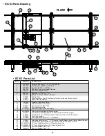
It is important that each bed section be checked for an out-of-square condition. If
conveyor is not square, tracking problems will result. Figure 4D indicates a racked
section.
TO CORRECT AN OUT-OF-SQUARE SECTION
1. Locate points on corners of section and measure distance “A” & “B”. If the
dimensions are not equal, the section will need to be squared. (Figure 4D).
2. After all bed sections have been checked and corrected for “racked condition”,
tighten all coupling channels and support frame bolts.
3. Make final check to see that all conveyor sections are level across width and
length. If entire conveyor is level, supports can be lagged to floor.
“Racked” conveyor sections will cause product to travel toward side of conveyor.
IMPORTANT!
Being out of level across this width of
conveyor can cause product drift on long conveyor lines.
FIGURE 4D
Содержание DC62
Страница 15: ...15 ...


