


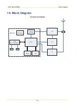


UHF1(400-470MHz)
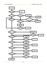
Troubleshooting Flow Chart
26
6.2
Receiver Circuit
Check Q6006,
Q6007
Check Q6004
Check Q6005 and
Front-end RF Circuit
No
No
Yes
Yes
Yes
Yes
Yes
Yes
No
No
No
No
No
No Recieve
No
Yes
Yes
Yes
No
Yes
No
No
Yes
3V3A_RX output is
normal?[1]
LNA_Out output is
normal?[8]
Yes
Complete
No
3V3A_RX_RF output
is normal?[2]
Check Q6005
The static working
point of Q6005 is
normal?[3]
The static working
point of Q6006/Q6007
is normal?[4]
Input IF signal via
U6001PIN47 to check
whether IF sensitivity is
normal?[5]
LO signal output is
normal?[9]
First IF output is
normal?[11]
Input signal is normal?[12]
Second LO is normal?[6]
18MHz is normal?[7]
RX_LO is normal?[10]
Check Q6003 and
peripheral components
Check Q6002 and
appropriate components
Check RX VCO
Check Z6001, Q6006, Q6007
and peripheral circuit
Check signal frequency, amplitude
and modulation information
Description of Normal Situations:
[1] Output voltage by Q6004 PIN3 is about 3.3 V.
Содержание PD502
Страница 1: ...PORTABLE...
Страница 5: ...VHF 136 174 MHz...
Страница 13: ...VHF 136 174 MHz Exploded View and Packaging Guide 7 3 2 Packaging Guide...
Страница 18: ...VHF 136 174 MHz Circuit Description 12...
Страница 43: ...PCB 3 9 PCB VHF 136 174 MHz...
Страница 44: ...PCB 3 VHF 136 174 MHz...
Страница 71: ...UHF1 400 470 MHz...
Страница 79: ...UHF1 400 470MHz Exploded View and Packaging Guide 7 3 2 Packaging Guide...
Страница 84: ...UHF1 400 470MHz Circuit Description 12...
Страница 108: ...UHF1 400 470MHz PCB 36 9 PCB...
Страница 109: ...UHF1 400 470MHz PCB 37...
Страница 136: ...1616300000260 2014 03 17 L07157 4...