
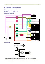


VHF (136-174 MHz)
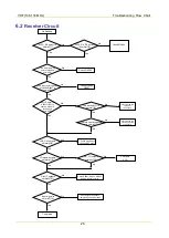
Circuit Description
23
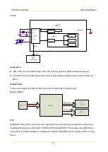
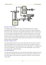
Frequency
Synthesizer
VCO_L
341.95-400MHz
RX
VCO_H
400-411.95MHz
RX
400-470MHz
TX
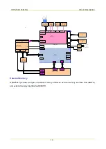
OMAP
Ref.Osc
19.2MHz
CV
SW
Adapt
SW
OP
DAC
TLV5614
MOD2+Freq error shift
MOD1
MCBSP2
From OMAP
MCSI1/SPI(CS1)
CV OUT
CV BUFFER
Adapt
Control
RX/TX
VCO Buffer
RX/TX
VCO Amplifier
LPF
BPF
680MHz-1040MHz
CV READ CTRL
LPF
TV/APC
OSC
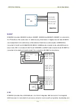
Operation Principle of PLL
The 19.2MHz frequency generated by the reference crystal oscillator goes to PLL for division,
generating the reference frequency (i.e. step frequency f1). Meanwhile, the frequency generated by
VCO goes into the PLL, where frequency f2 is generated through frequency division. Then frequencies
f1 and f2 are compared in the phase detector (PD), to generate continuous pulse current. The current
goes to the loop filter for RC integration, and is then converted to CV voltage. Then the CV voltage is
sent to the varactor of VCO. It adjusts the output frequency of VCO directly until the CV voltage becomes
constant. Then PLL is locked, and the stable frequency output by VCO goes to the TX-RX channel after
passing through two buffer amplifiers.
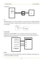
Operation Principle of VCO
VCO employs Colpitts oscillator circuit. There are two types of VCO: RX VCO and TX VCO. RX VCO
provides LO signal while TX VCO provides carrier for TX signal. When the oscillator is operating, it
obtains different output frequencies by changing the varactor's control voltage (i.e. CV voltage) and then
uses the control signals VCO_L_En and VCO_H_En to switch operating status. VCO_H is used for
receiving while VCO_L is used for transmitting.
Two-point Modulation
In TX mode, the two-point modulation technology is employed, to obtain higher modulation accuracy and
lower 4FSK bit error rate. MOD_H and Freq_TV send the modulation signal to the modulation end of
VCO and the reference crystal oscillator of PLL respectively to modulate TX VCO and the reference
crystal oscillator.
Содержание PD502
Страница 1: ...PORTABLE...
Страница 5: ...VHF 136 174 MHz...
Страница 13: ...VHF 136 174 MHz Exploded View and Packaging Guide 7 3 2 Packaging Guide...
Страница 18: ...VHF 136 174 MHz Circuit Description 12...
Страница 43: ...PCB 3 9 PCB VHF 136 174 MHz...
Страница 44: ...PCB 3 VHF 136 174 MHz...
Страница 71: ...UHF1 400 470 MHz...
Страница 79: ...UHF1 400 470MHz Exploded View and Packaging Guide 7 3 2 Packaging Guide...
Страница 84: ...UHF1 400 470MHz Circuit Description 12...
Страница 108: ...UHF1 400 470MHz PCB 36 9 PCB...
Страница 109: ...UHF1 400 470MHz PCB 37...
Страница 136: ...1616300000260 2014 03 17 L07157 4...