


VHF (136-174 MHz)
Circuit Description
21
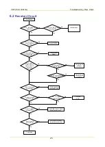
Tx/Rx Switch
S21:-0.2dB
S21:< -0.8dB
BW(-3dB):570MHZ
Stop band attenuation :-54dBc
AD9864
Band-pass Filter1
Low-Noise Amp
Band-pass Filter2
Mixer
IF Filter
IF Processor
IF Amp
OSC level:> 4dBm
S21:12dB
NF:< 3dB
Stop band attenuation(-2&IF1st) :-80dBc
IIP3:> 5dBm
TV1 /APC
S21:-7dB
NF:< -7dB
IIP3:> 20dBm
Center
Freq:73.35MHZ
S21:< -5dB
Adjacent
rejection(@25KHZ)
:> 42dBc
Stop band
attenuation(@-
4.5M):-85dBc
Gain:22dB
Po(-1dB):-22dBm
staic Ic:3.5mA
I/Q singal
S21:18dB
NF:< 1.2dB
IIP3:> 0dBm
S21:-2dB
S21:-5dB
Pi Attenuator
1
2
IL:0.5dB
Zin/Zout:470
R
Stop band filter
attenuation
coefficent >20dBc for
1st spurious image
frequence
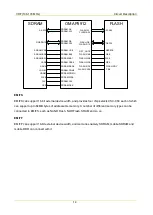
OMAP
Ref.Osc
19.2MHz
4CH DAC
TLV5614
P
i A
tt
enuat
or
1
2
ANT
LPF
TV/APC
MCBSP2
RX
VCO
Receiver Front-end
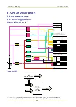
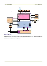
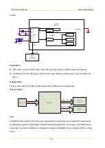
The HF signal from the low-pass filter passes through the electrically tunable band-pass filter controlled
via APC/TV1 level, to remove out-of-band interference signal and to send wanted band-pass signal to
the low-noise amplifier (Q6005). The amplified signal goes to a band-pass filter controlled via APC/TV1
level, to remove out-of-band interference signal generated during amplification, and to send wanted HF
signal to the mixer.
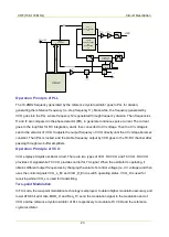
The wanted signal passes through the RF band-pass filter and low-noise amplifier and goes to the mixer
(D6009). Meanwhile, the first local oscillator (LO) signal generated by VCO passes through the low-pass
filter and also goes to the mixer (D6009). In the mixer, the wanted signal and the first LO signal are
mixed to generate the first IF signal (44.85MHz). Then the signal passes through the frequency selection
network composed of LC, to suppress carriers other than the first IF signal, and to increase the isolation
between the mixer and the IF filter. After that, the first IF signal is processed by the crystal filter (Z6001),
and is sent to the two-stage IF amplifier circuit (composed of PBR941) for amplification. Then the
amplified signal goes to the IF processor AD9864 (U6001) for processing.
Содержание PD502
Страница 1: ...PORTABLE...
Страница 5: ...VHF 136 174 MHz...
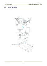
Страница 13: ...VHF 136 174 MHz Exploded View and Packaging Guide 7 3 2 Packaging Guide...
Страница 18: ...VHF 136 174 MHz Circuit Description 12...
Страница 43: ...PCB 3 9 PCB VHF 136 174 MHz...
Страница 44: ...PCB 3 VHF 136 174 MHz...
Страница 71: ...UHF1 400 470 MHz...
Страница 79: ...UHF1 400 470MHz Exploded View and Packaging Guide 7 3 2 Packaging Guide...
Страница 84: ...UHF1 400 470MHz Circuit Description 12...
Страница 108: ...UHF1 400 470MHz PCB 36 9 PCB...
Страница 109: ...UHF1 400 470MHz PCB 37...
Страница 136: ...1616300000260 2014 03 17 L07157 4...