8
torque value shown in the MAINTENANCE SCHED-
ULE.
NOTE: Whenever a wheel is removed, it will be neces-
sary to lubricate the wheel nuts and studs. (See
FIGURE 37.) Put two drops of engine oil (or other lubri-
cant) between the flange and body of the wheel nut. Also
put two drops of oil on the threads of the studs.
9447
3
1
2
1
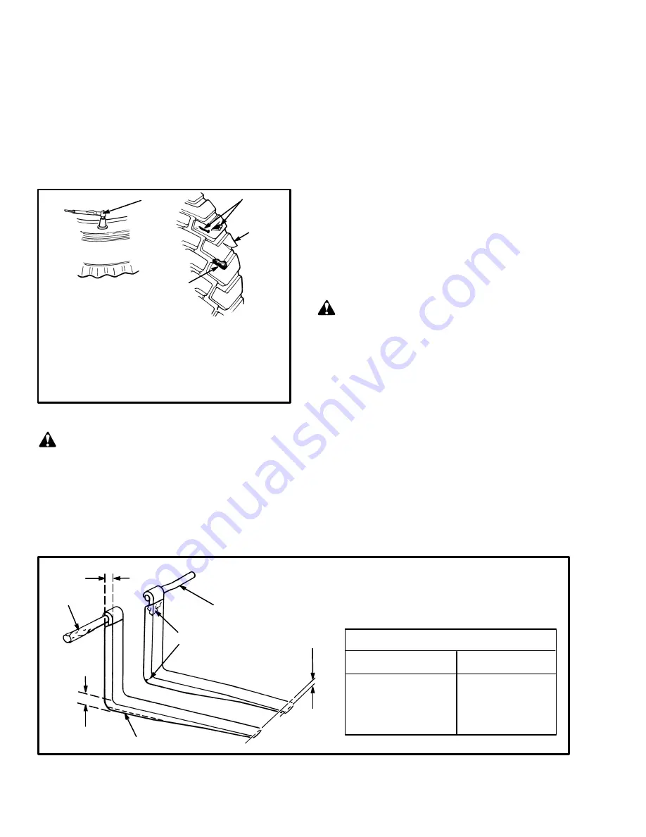
1. CHECK FOR DAMAGE (REMOVE NAILS,
GLASS AND OTHER OBJECTS FROM
THE TREAD)
2. MAKE SMOOTH EDGES
3. CHECK THE TIRE PRESSURE
(PNEUMATIC TIRES)
FIGURE 4. CHECK THE TIRES
CAUTION
When the wheels have been installed check all wheel
nuts after 2 to 5 hours of operation. Tighten the nuts
in a cross pattern to the correct torque value shown
in the MAINTENANCE SCHEDULE table. When
the nuts stay tight after eight hours, the interval for
checking the torque can be extended to 150 hours.
Forks
The identification of a fork is determined by how it is
connected to the carriage. These lift trucks have pin
forks. Pin forks are fastened to the carriage with large
fork pins.
Forks, Adjustment
A lock pin for each fork fits into the top carriage bar and
a slot in the fork. These lock pins hold the fork in posi-
tion. Adjust the forks as far apart as possible for maxi-
mum support of the load. Make sure the lock pin is en-
gaged in the carriage bar and the fork. The fork must be
locked into position after the adjustment is made.
Forks, Removal
WARNING
Do not try to move a fork without a lifting device.
The forks can weigh up to 370 kg (800 lb) each.
Put the lift truck on a level surface and lower the forks.
Tilt the mast so that the forks have stability. Remove the
retainers for the fork pins and push the pins from the car-
riage. Move the lift truck away from the forks.
Forks, Installation
1. Put the forks approximately 1 m (3 ft) in front of the
carriage.
2. Slowly move the lift truck toward the forks until the
fork pins can be installed. Install the fork pins and the
retainers.
3. FORK PIN DAMAGE
4. MUST BE 90% OF
DIMENSION X
5. FORK WEAR
1
5
3
3
2
11195
FIGURE 5. CHECK THE FORKS
X
4
1. TIP ALIGNMENT
(MUST BE WITHIN 3%
OF FORK LENGTH)
2. CRACKS
FORK TIP ALIGNMENT
LENGTH OF FORKS
3% DIMENSION
1220 mm (48 in)
37 mm (1.45 in)
1830 mm (72 in)
55 mm (2.15 in)
2440 mm (96 in)
74 mm (2.90 in)


