background image


User manual R3 

DLCP 


- 8 - 

2.5


Add-ons 

2.5.1


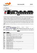
DLCP Input board 


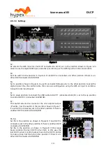
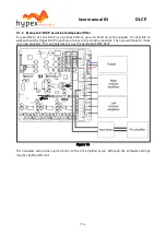
Figure 3 

 
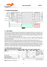
The DLCP can be used as a digital pre amplifier when the optional “DLCP input board” is bought. This 
input  board  can  be  connected  to  the  DLCP  with  only  2  flat  cables.  You  can  increase  the  number  of 
analogue  inputs  to  4  balanced  stereo  analogue  inputs.  It  has  four  digital  inputs;  USB  audio,  AES 
(XLR/RJ45

1

), S/PDIF and Optical in. It has two digital outputs; AES (XLR/ RJ45

1

) and S/PDIF.  

It’s  possible  to  connect  two  DLCP’s  with  only  one  input  board.  J5/J5B  can  be  used  to  connect  the 
third DLCP, or the second DLCP if it’s not in the same case. The control and digital outputs of the first 
DLCP  (connected  to  J2/J3)  and  analogue  inputs  are  linked  trough  the  inputs  of  the  second  DLCP 
(connected  to  J2B/J3B).  Three  or  more  DLCP  modules  can  be  connected  together  with  a  straight 
through (8-wire) cat5 cable with RJ45 connectors. The bus is specified and tested for cables up to 10 
meter. 

Note 1:


Switchable on PCB. See


“Settings” for information about the right positioning of the switch-

es.


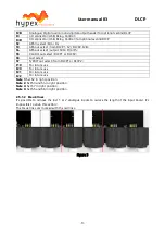
2.5.1.1


Connections 


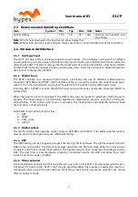
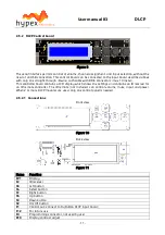
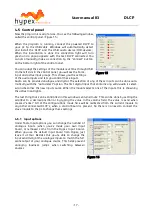
Figure 4 

 
Name 

Function 

J1 

Mounting block 

S1 

USB switch (switch between DLCP 1, J3 / DLCP 2, J3B) 

J6 

USB connector 

J4 

Control in (If this connector is used, don’t use J4B)

      4)


J4B 

Control in (If this connector is used, don’t use J4)      

4)


J5 

Control out (If this connector is used, don’t use J5B) 

4)


J5B 

Control out (If this connector is used, don’t use J5)

      4)


J8 

Digital AES/EBU input    

1)


J9 

Digital AES/EBU output 

2)


J18 

Digital optical input 

J7 

Digital S/PDIF in- and output 

3)

 (red=input, white=output) 

J10 

Analogue 1 left input 

J11 

Analogue 1 right input 

J12 

Analogue 2 left input 

J13 

Analogue 2 right input 

J14 

Analogue 3 left input 

J15 

Analogue 3 right input 

J16 

Analogue 4 left input 

J17 

Analogue 4 right input 

J2 

Analogue/Digital audio in and digital output header 

Содержание DLCP

Страница 1: ...Hypex Electronics BV Kattegat 8 9723 JP Groningen The Netherlands 31 50 526 4993 sales hypex nl www hypex nl User Manual R3 Digital Loudspeaker Cross over Platform DLCP...

Страница 2: ...s preamplifier 13 3 1 2 Example 2 DLCP as active loudspeaker filter 14 3 2 Application notes 15 4 Hypex Filter Design 16 4 1 Target response 16 4 2 Driver correction 16 4 3 Crossover design 16 4 4 Sof...

Страница 3: ...Analogue and digital inputs Digital balanced audio loop through Low jitter discrete clock oscillator Balanced audio in and out Six channel active filtering Fully user configurable filters Firmware upd...

Страница 4: ...board to increase the number of analogue stereo inputs to 4 Link communication only with two or more modules and in combination with a controller 1 4 Applications High end consumer audio Digital pre a...

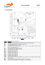
Страница 5: ...t is connected with J16 J5 Gain adjust header analogue left input J8 Gain adjust header analogue right input J17 Standby supply connector J10 Analogue audio output ch1 J11 Analogue audio output ch2 J1...

Страница 6: ...ocessing including volume control is done using the on board DSP digital signal pro cessor The module has six Molex Microfit audio outputs which can be used to connect NC400 buffered UcD ST and HG mod...

Страница 7: ...te converter ASRC to reduce jitter When the input is set to Auto detect the ASRC chip scans its inputs for whichever digital signal is present The input source is automatically switched to digital whe...

Страница 8: ...cted together with a straight through 8 wire cat5 cable with RJ45 connectors The bus is specified and tested for cables up to 10 meter Note 1 Switchable on PCB See Settings for information about the r...

Страница 9: ...ntrol out select DLCP1 or DLCP2 S6 Last select S7 S PDIF out select from DLCP1 or DLCP2 J19 For future use J20 For future use J21 For future use J22 For future use Note 1 Set S2 in right position Note...

Страница 10: ...e input boards S1 Set in down position to connect the USB cable to DLCP 1 connected to J2 J3 set in the up position to control DLCP 2 connected to J2B J3B S7 This switch selects the source for the cin...

Страница 11: ...LCD display which shows the settings and contains an IR receiver for an IR remote controller The IR remote not included can control volume mute input and power When 2 or more DLCP modules are used on...

Страница 12: ...ettings equal for all the DLCP s in the chain The sources for the output channels can be different for each DLCP e g to use all six channels on the first DLCP for the left loudspeaker and the second D...

Страница 13: ...ed as a high end active pre amplifier This example doesn t use the dedicated SMPS DLCP Figure 13 The DLCP can be connected to the input board with two flat cables J2 on the input board must be connect...

Страница 14: ...ld an active speaker It s possible to work without the Hypex DLCP input board to keep it as small as possible Then you will have to make your own adapters This example doesn t use the dedicated SMPS D...

Страница 15: ...all to chassis with a metal spacer for optimum EMI performance Please use the amp_enable pin to guarantee a pop free startup and shut down of the connected am plifier Please use the XLR input balanced...

Страница 16: ...ed to equalize the drivers s phase response The phase response gets automatically equal ized as the magnitude response is corrected using minimum phase EQ A consideration to be made is whether to iron...

Страница 17: ...ption The first digital input that contains any valid audio is select ed and becomes the new input source When the module selects one of the inputs this is shown by the active input lights The last th...

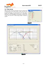
Страница 18: ...gned in the Filter design Under view there can be switched between the control panel and the filter design window The following pages will give you a widespread instruction of the possibilities of the...

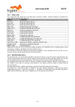
Страница 19: ...d or disabled in the filter definition area The impulse or step tabs show the time domain response of the imported drivers and the sum re sponse and are used to demarcate the anechoic portion 4 6 2 Fi...

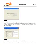
Страница 20: ...ocessor sampling rate is that of the Hypex DSP hardware Note that this setting does not control the sampling rate of the hardware Rather it informs the filter design application of what that sampling...

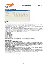
Страница 21: ...woofer Ch6 Right subwoofer Please note that these settings are overruled by an control board if it s connected 4 6 6 Work flow Measuring using the DSP unit set to flat Perform impulse response measure...

Страница 22: ...icient information is available to make any correction below this frequency A way of obtaining quasi anechoic low frequency measurements is making close up measurements Working with such measurements...

Страница 23: ...ency Q gain Dip peak filter For peaks Q is defined by the poles For dips Q is defined by the zeros Thus the same filter with op posite gains will cancel The first step is equalizing the magnitude resp...

Страница 24: ...cted the update begins DO NOT DISCONNECT THE MODULE AT THIS POINT When the progress bar is filled the update is completed On a CRC error the update is automatically restarted after three errors the up...

Страница 25: ...ild as would be expected Figure 24 The first reflection arrives after 8ms so this plot conveys no meaningful information about the re sponse below 200Hz Not shown is a separate close up measurement of...

Страница 26: ...Figure 25 The strategic placement of in total just 32 poles and 32 zeros corrects the response of this seeming ly hopeless loudspeaker to within 1dB or 0 3dB 3rdoctave smoothing Considering that fur t...

Страница 27: ...xes are picked apart with great ease too much so perhaps for home use and the subtlest of EQ changes become very obvious Stereo imaging is un characteristically good in all 3 dimensions for the low co...

Страница 28: ...User manual R3 DLCP 28 5 Dimensions 5 1 DLCP Top view Side view...

Страница 29: ...l R3 DLCP 29 5 2 DLCP input board Top view Please download the 2D 3D files from our website 5 3 DLCP control board Front view NOTE RJ45 connector not on picture Please download the 2D 3D files from ou...

Страница 30: ...quipment whose failure can reasonably be expected to result in injury or death is not permitted except by explicit written consent from Hypex Electronics BV Warranty The work carries warranty out for...

Отзывы: