User manual R3
DLCP
- 6 -
2
System information
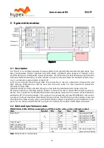
Figure 2
2.1
Description
The “DLCP” is a complete hardware/firmware platform for digitally filtered and corrected active mul-
tiway loudspeakers. Digital response correction allows significant extra degrees of freedom in the
acoustic design of a loudspeaker. Driver parameters can be selected for best efficiency and distortion
instead of electrical damping, and the cabinet can now be fully optimized for radiation pattern. Figu-
re 2
is a schematic representation of the DLCP.
A PC can control the DLCP through USB. This connection is used to upload the configuration and
filter settings, USB-audio can also be send thru the same cable. It is also possible to update the
firmware through USB.
Optional remote control is effected through a 4mA optically isolated current-mode serial link.
All signal processing, including volume control, is done using the on-board DSP (digital signal pro-
cessor). The module has six Molex® Microfit® audio outputs, which can be used to connect NC400 /
buffered UcD™ ST and HG modules. The supply can be provided by the new DLCP SMPS or the auxilia-
ry output of a Hypex Switched Mode Power Supply module. The DLCP can go into standby mode and
shut down the power supply, when an external standby voltage is applied and a controlboard is pre-
sent. You can create a chain of DLCP’s (up to 6!) to increase the number of DSP filtered channels.
2.2
Brief audio performance data
MBW=20kHz (20Hz-20Khz), unweighted, all filters set to unity, unless otherwise noted
Item
Symbol
Min
Typ
Max
Unit
Notes
Input level
1)
V
IN
24.25
dBu
Gain adjust 0dB
17.95
Gain 6dB
12
Gain 12dB
9
Gain 15dB
Output level
V
OUT
2.59
V
0 dBFS
DSP sampling rate
Fs
93.75
kHz
ADC sampling rate
Fs
93.75
kHz
Supported digital sampling rates
Fs
32, 44.1, 48, 88.2, 96,
192
kHz
All input rates con-
verted to 93.75kHz
Note 1:
See J5/J8 in Connections


