
ENGINE 3-16
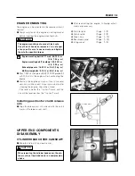
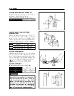
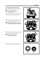
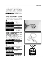
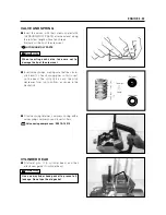
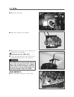
1. Insert with a slight rotation, the solid pilot that
gives a snug fit. The shoulder on the pilot
should be about 10㎜ from the valve guide.
2. Using the 45�cutter, descale and cleanup the
seat with one or two turns.
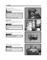
3. Inspect the seat by the previous seat width
measurement procedure. If the seat is pitted or
burned, additional seat conditioning with the
45�cutter is required.
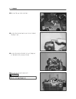
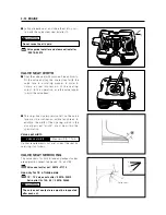
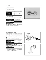
If the contact area is too low or too narrow, use the
45�cutter to raise and widen the contact area. If
the contact area is too high or too wide, use the
15�cutter to lower and narrow the contact area.
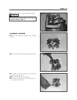
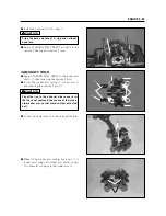
4. After the desired seat position and width is
achieved, use be 45�cutter very lightly to clean
up any burrs caused by the previous cutting
operations. DO NOT use lapping compound
after the final cut is made. The finished valve
seat should have a velvety smooth finish and
not a highly polished or shiny finish. This will
provide a soft surface for the final seating of the
valve which will occur during the first few sec
onds of engine operation.
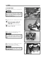
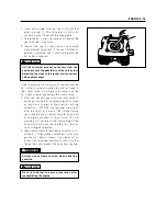
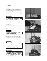
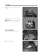
5. Clean and assemble the head and valve com-
ponents. Fill the intake and exhaust ports with
gasoline to check for leaks. If any leaks occur,
inspect the valve seat and face for burrs or other
things that could prevent the valve from sealing.
Cut the minimum amount necessary from the
seat to prevent the possibility of the valve stem
becoming too close to the rocker arm for correct
valve contact angle.
CAUTION
Be sure to adjust the valve clearance after
reassembling the engine.
CAUTION
Always use extreme caution when handling
gasoline.
WARNING
Содержание RX 125 -
Страница 1: ...SERVICE MANUAL 99000 97100 SERVICE MANUAL HYOSUNG MOTORS MACHINERY INC RX125 RX 125 ...
Страница 5: ......
Страница 29: ...PERIODIC MAINTENANCE 2 16 ...
Страница 94: ...FUEL SYSTEM 4 12 Start motor Piston Cylinder Oil cooler Cylinder head Crankcase Transmission ...
Страница 113: ...6 1 CHASSIS FRONT WHEEL REMOVAL Support the machine by jack block or service stand Service stand 99000 99094 ...
Страница 117: ...6 5 CHASSIS Install the disk with four bolts as shown in photo Disk bolt 18 28 N m 1 8 2 8 kg m ...
Страница 118: ...CHASSIS 6 6 FRONT BRAKE yyy yyy yyy yyy yy yy y y ...
Страница 126: ...CHASSIS 6 14 FRONT FORK ...
Страница 132: ...CHASSIS 6 20 STEERING STEM ...
Страница 143: ...6 31 CHASSIS SUSPENSION Service limit 10 20 mm Service limit 14 20 mm Service limit 10 20 mm ...
Страница 150: ...CHASSIS 6 38 SPACER Apply grease to the spacer when installing Super grease A ...