29
Operation and maintenance manual, Discfilter HSF2200-1/2F PFC
7.3 Filter panels
NB Prior to servicing, read section 2.7.
7.3.1 High pressure cleaning
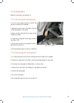
It may be necessary to manually clean the filter panels. The need of manual cleaning becomes
clear if the frequency of automatic backwash starts increases. Manual cleaning can be perfor-
med with a high pressure washer.
When using a high pressure washer a wash pressure of max. 80 bar may be used. Never
hold the cleaning nozzle directly against the filter media.
7.3.2 Chemical cleaning of filter panels
Long-term clogging of the filter media can be caused by, among other things, iron, calcium or
organic fouling. This clogging can normally be removed through chemical cleaning. Three proven
products that do not affect the life of the filter media are dilute hydrochloric acid (HCl), dilute
sodium hypochlorite (NaClO) and dilute sodium hydroxide (NaOH).
The use of other types of cleaning agents may cause damage to equipment.
The cleaning products must not be mixed. If, for example, HCl and NaClO are mixed this
produces toxic chlorine gas. HCl and NaOH are highly corrosive. For safety advice, see app-
licable local regulations.
For more detailed instructions, please contact your supplier.
Hydrotech Discfilters in the HSF2200 series as standard are prepared with a chemical ramp to
make removal of long-term clogging of the filter media possible.
The Hydrotech chemical trolley HCT (option) is connected to the chemical ramp connection (see
Figure 3.2 and Figure 3.5). The control system is prepared and programmed for connection of
a dosage system. After completing electrical and mechanical connection, chemical cleaning is
started as follows:
1. Turn the mode selector to AUTO mode (see Figure 5.1).
2. Set the number of cleaning sequences with the CLEANING SEQUENCE selector (see Figure 5.1).
3. Start chemical cleaning with the CLEANING START switch (see Figure 5.1).
Once cleaning is completed the filter automatically returns to normal operation in AUTO mode.
If necessary clean the chemical ramp’s nozzles as set out below:
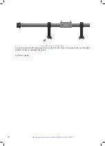
1. Remove the nozzle by turning it ¼ turn anticlockwise (see Figure 7.9).


