background image


                                                                                                                                                Page 28

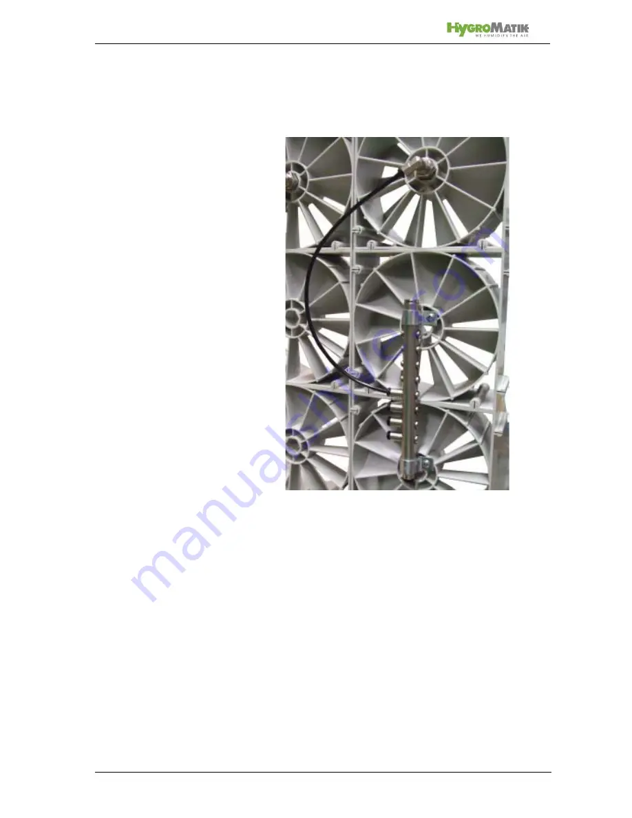
The completed finished hose connection should look like this: 

Manifold - Pump Station 

In the standard version a 6/4 hose leads from the pump station
to a manifold. However, if the LPS nozzle system is equipped
with a partial/full load switch, then there is a 6/4 hose line lead-
ing to two manifolds. 

Since the 6/4 hose line goes through the air conditioning duct a
duct wall grommet is provided (or two in the case of a partial/full
load switch). 

Содержание LPS

Страница 1: ...LPS Humidifies and Cools ÁLPS Ä4 3Ö ENhÈ LPS 20130619 EN Operating manual ...

Страница 2: ... 19 LPS All Rights reserved HygroMatik GmbH grants the legal user of this product or device the right to use the Work s solely within the scope of the legitimate operation of the product or device No other right is granted under this licence In particular and without prejudice to the generality of the foregoing the Work s may not be used sold licensed transferred copied or reproduced in whole or i...

Страница 3: ...roplet separators optional 15 4 2 6 Humidification section 15 4 3 Partial and Full Load 16 5 Connnections 17 5 1 Water 17 5 2 Waste water 17 5 3 Pressure water 17 5 4 Electrical 18 6 Interfaces to the HygroMatik nozzle system LPS 19 6 1 Air 19 6 2 Humidification chamber 19 7 Mechanical assembly 21 7 1 Overview of the humidification chamber 21 7 2 Vortex wall module assembly 22 7 3 Assembling the v...

Страница 4: ...ty chain 44 11 3 Circuit diagram 45 11 4 Inspecting the electrical installation 47 12 Commissioning 48 13 Maintenance 49 13 1 Maintenance activities 49 13 1 1 Inspection replacement of the net based water filter 50 13 1 2 Cleaning the atomizer nozzle 51 13 1 3 Cleaning the droplet separators 52 13 1 4 Cleaning the vortex module wall 52 13 1 5 Cleaning the humidification chamber 53 14 Control Syste...

Страница 5: ...4193 895 0 Switchboard Tel 49 0 4193 895 293 Technical Hotline Fax 49 0 4193 895 33 Email hot1 HygroMatik de Please have your device data ready for queries or spare part orders 1 1 Typographic markings lists with items beginning with bullets general lists lists with items beginning with arrows work or operating steps which should or must be carried out in the speci fied order installation steps wh...

Страница 6: ...g manual at the location where the device is being used The HygroMatik LPS nozzle system is not frost proofed and not suitable for outdoor installation The room temperature should be between 5 and 40 C At an altitude of over 1000 meters please contact your HygroMa tik dealer or HygroMatik for details Applications The HygroMatik LPS nozzle system has a wide range of applica tions These systems are ...

Страница 7: ... Control or only after consultation with HygroMatik The default constant pressure level of the HygroMatik LPS noz zle system may not be changed or only after consultation with HygroMatik The HygroMatik LPS nozzle system may only be used for the purpose of cold water cooling after consultation with HygroMa tik The HygroMatik LPS nozzle system or may not be used in a ver tical flow or only after con...

Страница 8: ...ormation Observe all safety instructions and warnings found on the sys tem If malfunctions occur switch the system off immediately and secure it to prevent it from being switched on Eliminate the mal functions immediately After maintenance work has been carried out expert staff must ensure that the system is safe to operate Only use original spare parts National regulations beyond the scope of thi...

Страница 9: ...d to IP20 Ensure that the devices are protected from dripping water and dust at the installation location If a HygroMatik LPS nozzle system is to be set up in an area without water drainage safety measures which eliminate the possibility of water entering the system due to leaks must be taken Electrical equipment Caution Only a qualified electrician is permitted to work on the electrical system an...

Страница 10: ...rfect condition Note Any transport damages and or missing parts must be re ported immediately to the shipper or supplier The periods in which notification of the transport company must occur for the purposes of identifying the damage are as follows Periods are subject to change without notice 3 5 Scope of delivery The following items are included in the delivery vortex modules droplet separators o...

Страница 11: ...to the nozzles These nozzles generate a very fine spray mist which is taken up by the air in the device chamber The ambient air is cooled adia batically in the process 4 2 Design and process 1 Pump group 2 Water feed 3 Vortex module wall 4 Viewing window necessary according to VDI 6022 5 2 stage droplet separator 6 Humidification chamber or duct with service doors and water tray 7 Water drain siph...

Страница 12: ...tenance free asynchronous motor with variable frequency ena bles continuous operation up to 50 Hz 4 2 2 Dimension drawing of HygroMatik LPS nozzle system Pump group Capacity l h Max speed rpm LPS 45 45 1350 LPS 72 72 1350 LPS 110 110 1350 H T B Weight LPS 45 110 700 230 600 30 Kg T B H ...

Страница 13: ... shear zones which lead to a homogeneous distribution of moisture along the humidification section 0 9 m The vortex modules dimensions 150 x 150 mm are delivered individually and can be assembled to form a wall For optimal moisture absorption the air velocity is 1 0 2 5 m s The vortex module wall exhibits a low pressure drop of 10Pa at an air veloc ity of 2 0 m s ...

Страница 14: ...nstream of the vortex modules The air and aerosols are mixed intensively here The atomising nozzle generates a spray cone with a wide open ing angle 1 Nozzle opening 2 Nozzle body Functioning The nozzle sets the flowing water in rotation and thereby it can leave at high speed This enables a very fine water spray The higher the operating pressure the finer the droplets Material of the nozzle corros...

Страница 15: ...oMatik The droplet separators are inserted into the humidification chamber via guide rails and are hence easy to remove for serv icing The traps are standardly delivered with corrosion resistant metal frames Note Hygiene compliance checks applies only to systems with droplet separators 4 2 6 Humidification section The section between the vortex module wall and the droplet sep arators is called the...

Страница 16: ...er At Partial load a sole noid valve switches off the water supply for approximately half of the nozzles Construction The vane pump has to exits for water one is the water supply for the nozzles for Partial load and the othe one is the water sup ply for the nozzles for Full load If the external control signal decreases below a special switching point the HygroMatik nozzle system LPS switches off t...

Страница 17: ... with VDI 6022 i e from a microbiological point of view it must be of drinking water quality 5 2 Waste water Connection Connecting piece DN 12 for plastic hose resistant to low conductive water Fitting with constant fall and free outlet and siphon 5 3 Pressure water Connection Full Load plug in connection for 6 4 pressure hose Connection Cooling plug in connection for 6 4 pressure hose Connection ...

Страница 18: ...ed socket 16 A at the installation site is necessary External control signal 0 10 V DC 4 20 mA DC System enabling via ext potential free contact Collective fault signal potential free contact change over contact Operating status signal potential free contact NO ...

Страница 19: ...umidified air must exhibit a purity in terms of bacterial count in accordance with VDI 6022 6 2 Humidification chamber The humidification component should be designed with a floor tray that has an inclination of at least 1 5 towards the trap and to be waterproof The water drain must be at the end of the humidification section The ideal humificiation section length distance between vortex module wa...

Страница 20: ...s can be removed for servicing there cannot be any stagnant water Note When starting the system check again that the humidifica tion chamber has been thoroughly cleaned In particular the humidification chamber and the ventilation duct upstream of it must be free from metal swarfs to prevent corrosion ...

Страница 21: ...eparators 4 Lower guide rails for droplet separators 5 Collection tray 6 Drain with trap 7 Guide rails for vortex module wall 8 Humidification section 0 9 m 9 Two supplied bushings for the duct for partial load full load switching for connecting high pressure hoses Only one bush ing is needed for the standard model 10 Distribution pipe Note In front of the vortex module wall and from the droplet s...

Страница 22: ...de bars 1 7 3 Assembling the vortex module wall Two guide rails are required for assembly of the vortex module wall We recommend to have an air gap sideways between the vortex module wall and the housing wall as it generates a laminar air flow and prevents moisture build up on the walls 7 3 1 Guide rails for the vortex module wall In order to position the vortex module wall in the humidification c...

Страница 23: ... mm Hight please see above sketch Material 1 4301 stainless steel sheet thickness 1 mm 7 3 3 Side rails for the vortex module wall If the wall consists of 11 or more vortex module rows side rails are required in order to avoid bending of the vortex module wall Having more than 16 vortex modules in horizontal position the the vortex module wall has to be vertically separated into two halfs that are...

Страница 24: ...op vortex module The side rail is an u section and made of stainless steel It is 1 5mm thick For the assembling the open side of the u section has to be attached to the latteral edge of the vortex module wall pos 3 The lower end of the side rail is positioned in the middle of the lowest vortex module The lowest drilling pos 2 of the side rail is used to screw in a self tapping screw M3 9X20 A seco...

Страница 25: ...h the supplied nozzle assembly data sheet locate the vortex module to be equipped with a nozzle Then plug the nozzle body 1 as shown in the picture on the upstream side of the vortex module so that it protrudes about 1 cm on the other side Screw the nozzle 2 and copper washer 3 firmly into the nozzle body 1 2 3 ...

Страница 26: ...ding port on the manifold the water hose must have a constant slope Installation A manifold is mounted on the inlet side to at least two vortex modules Determine distributor pipe position 1 on vortex wall in accordance with nozzle data sheet Place retaining clips 3 on the appropriate position on Vortex Modules Put screw 2 through by retaining clip Vortex Module Tighten nut 4 with washer 5 on the r...

Страница 27: ...he manifold pipe Check connection by gently pulling on the hose Estimate the hose length noting nozzle assembly plan to the nozzle by observation Minimum bending radius no less than 25mm Cut the hose at right angles with a hose cutter Insert hose into the nozzle snap connector Check connection by gently pulling the hose ...

Страница 28: ...hose leads from the pump station to a manifold However if the LPS nozzle system is equipped with a partial full load switch then there is a 6 4 hose line lead ing to two manifolds Since the 6 4 hose line goes through the air conditioning duct a duct wall grommet is provided or two in the case of a partial full load switch ...

Страница 29: ...e wall of the air conditioning duct Assemble snap connector 4 nut 3 and washer 2 to hose opening 1 and insert through the duct wall from the outside see picture below From the inside of the duct assemble washer 5 mother 6 and necessary snap connectors 7 and screw tight 1 2 3 4 5 6 7 ...

Страница 30: ... pulling the tube Estimate the hose length to the ducting snap connector external duct wall Maximum bend radius 40mm Cut the hose at right angles with a hose cutter Put the 6 4 hose line into the ducting angled snap con nector external duct wall Check by gently pulling the tube Put a further 6 4 hose line into the straight snap con nector internal duct wall Connection I Water supply for nozzles fo...

Страница 31: ... cutter Put the 6 4 hose line into the angled snap connector on the duct opening external duct wall Check by gently pulling the tube Partial full load switching The tubing for partial full load switching is initially in the same as described above for the standard version In addition though there is a further pump station hose for optional output II for full load operation to a second manifold on ...

Страница 32: ... Detail A Dimensions given in mm A1 Trap guide rail U section with perforated 1 4301 stainless steel sheet A2 Trap guide rail holder U section made from 1 4301 stain less steel A3 Several holes at least 4 per metre 8 10 mm in diameter distributed over the length of the trap holder A4 Collection tray for humidification chamber A5 Fixation of guide rail with the floor of the humidification chamber e...

Страница 33: ...vets or similar Assembling two droplet separators in a stack For installation heights of above 1 5 m two droplet separators must be mounted in a stack The waste water from the upper droplet separator is drained via an additional collector For this the waste water from the upper trap is drained via a flexible hose either directly or into the collec tion tray This additional collector is to be provi...

Страница 34: ...onnection for drainage of waste water from upper droplet separator Perforated sheet metal material 1 4301 should be used for the lower guide rails for the droplet separators Alternatively sheet metal with several holes at least 4 per metre 8 10 mm in diam eter can be used The assembly must be made with 1 5 incline ...

Страница 35: ...r screws and rawlplugs are included for hanging the unit housing Firstly holes are to be drilled according to the pump station dimensions see pump station dimen sions Press rawlplugs into the drilled holes if dealing with stone or con crete walls Then screw the top two fittings to the wall allowing a 12mm distance from the screw head to the wall and hang up the pump station Then attach and tighten...

Страница 36: ...t of 11 modules is the Vortex Vortex module supported by two side rails With16 Vortex modules is it vertically split and sup ported individually by side rails Droplet separator assembly Are the guide rails built so that separator can be lifted or slid from the guide rails Is it ensured after assembly that the floor pan is sho wing no leaks Are all electrical plug connections secure Mounting of the...

Страница 37: ...Page 37 8 Dimensions Pump Station View from below Side view Rear view ...

Страница 38: ... drainage 3 12mm plastic tube 1 5 meter included 4 plastic hose DN12 on site 5 Water filter input side 3 4 external thread output side 12mm snap connector 6 Mounting Bracket 7 Pump Station 8 External drain siphoned free entry must be assured 9 Manometer 0 10 bar 7 1 2 5 4 3 6 8 9 ...

Страница 39: ...pply Locate water Filter position 5 in the graph above near the pump station 7 Transfer mounting bracket hole pattern 6 to a suitable location on wall Then drill using rawplugs and mounting brackets inclu ding water filters An 8mm plastic tube is supplied length 1 5 m shorten if necessary Connect this to the snap connector on the output side of the water filter Gently pull on the hose to check for...

Страница 40: ...n the graph above is attached to the DN12spout on the bottom and made fast with a clamp The tube is then siphoned off and installed on the slope to the drain 8 9 3 1 Water drain for the humidification chamber Note The water drain in the collection tray must be at the lowest point in the humidification chamber It is recommendable to have the water drain positioned behind the droplet separators with...

Страница 41: ...upplied water filter installed to the water inlet for the pump station Is the feed water quality within the specified range Is the hose that lies between the water filter and pump station waterproofed Drainage Is the drain hose siphoned and installed with a constant incline to the drain Can the flushing water drain off freely Humidification chamber Is the humidification chamber provided with a dra...

Страница 42: ...ng in accordance with VDI6022 In order to carry out a visual inspection according to VDI 6022 sufficiently large windows removable panels have to be pro vided in the area of the droplet separators and the vortex mod ules 10 2 Automatic flushing If the HygroMatik nozzle system LPS is in stand by mode and there is no demand for work for 24 hours the system will periodi cally run every 24h flush cycl...

Страница 43: ...components from damage by electro static discharge special measures must be taken during all installation work Caution During installation please perform the following steps Disconnect the system from the mains supply and secure it to prevent it from being switched on again Ensure that the system is de energised Installation and removal of the control system may only be performed if the device is ...

Страница 44: ... contacts such as max hygrostat air flow relay duct pressure switch ventilator interlock etc are placed in series between series terminals X2 1 and X2 2 safety chain Caution If the ventilation system fails or the supply air face velocity is too low less than 0 9 m s the built in control must switch off the humidifier via the safety chain Otherwise unde sired condensate build up behind the droplet ...

Страница 45: ...2 20 A1 A1 A2 A2 19 21 SE632 origin Ers d Ers f page 1 of 1 p drawing Nr description file modification date name edit Norm date LPS Options Supply 230VAC control signal HP sensor 0 20mA water supply pressure switch interlock potential free input winter summer Mode operation message collective fault Fan 230V MV 230V water inlet valve MV 230V full load winter MV 230V flushing MV 230V part load winte...

Страница 46: ...5 AI3 AI4 DI4 1 2 6 8 7 3 5 4 5 GND 3 G 4 A03 DO6 12V DO1 DO2 DO3 DO4 AO Supply Supply LAN 10 7 9 8 A04 DO1 DO2 DO3 A02 0 V 12V L N L N C1 F2 5AF N PE 50 C B1 DI6 DI1 1 2 K1 K1 K2 20 A1 A1 A2 A2 19 SE632 Supply 230VAC control signal HP sensor 0 20mA water supply pressure switch interlock potential free input winter summer Mode operation message collective fault Fan 230V MV 230V water inlet valve M...

Страница 47: ...icity supply company Does the mains voltage match the voltage specified on the nameplate delivery note Have all electrical connections been carried out accord ing to the connection diagrams Have all electrical screw and plug cable connectors been attached properly Are the switch off conditions for protection in case of faults complied with Has the system been earthed The system can then be switche...

Страница 48: ...tch Pos I Set commissioning control to permanent demand steam production The following functions begin A self test When humidity is demanded the pump vane is operated and directs the water at a pressure of up to 16 bar to the nozzle The water is atomized at the nozzle All nozzles should not drip and show an even spray pattern Further tests All electrically powered functions must function Observe L...

Страница 49: ...ed staff to determine whether it is safe to operate 13 1 Maintenance activities For the system to operate without any problems the following checks and maintenance tasks must be carried out regularly 1 x per month Check housing for contamination and clean if neces sary Carry out a visual inspection of droplet separators and clean if necessary Check the water filter cartridge upstream of the pump f...

Страница 50: ... If the white water filter cartridge changes its colour this means it is polluted Pollution causes a higher flow resistance This reduces the water pressure at the pump Too little pressure can cause the nozzle system to switch off dry run protection Replacing the water filter 1 2 3 1 Filter housing holder 2 Filter cartridge inside lying 3 Filter housing 4 Mounting plate 4 ...

Страница 51: ... nozzle 1 Switch the HygroMatik LPS Nozzle System power supply to 0 2 Unscrew the nozzle from nozzle holder Take care not to touch the impact pin 3 Unscrew the nozzle by screwing the inside part out 4 Clean the nozzle components in an ultrasonic bath for about 10 minutes if necessary use a lime remover in low concentra tion less than 10 5 Put nozzle components back together 6 Screw nozzle in the n...

Страница 52: ...annual maintenance Any contaminants must be removed with a cleaning agent Cleaning the droplet separators 1 Pull or lift the droplet separators out of the guide rails 2 Clean the droplet separators with a cleaning agent and then rinse and dry them 3 Carry out a visual inspection of the droplet separators repeat the cleaning step if necessary and replace the droplet separa tors if damaged 4 Place t...

Страница 53: ...cleaning and disinfection we recommend INCIDUR pro duced by Ecolab When using other cleaning and disinfection agents please check material compatibility with all plastic materials used in the humid ification chamber Caution Do not aim the water jet at the droplet separators Any upstream or downstream heating or cooling units must not become wet during cleaning ...

Страница 54: ... display A frequency inverter Item 2 supplies different frequencies and voltages for the asynchronous motor of the pumping station located in the lower part of the system cabinet Depending on the speed of the pump it is possible to vary the water pressure and thereby the quantity of water atomized The water pressure may range between 5 and 16 bars The main switch Item 3 which is located at the top...

Страница 55: ...2 Summer winter mode The HygroMatik low pressure nozzle system can be operated in summer or winter mode In winter mode the HygroMatik low pressure nozzle system is used to regulate air humidity whereas summer mode is used for exhaust air cooling Changeover between summer and winter modes is made by potential free contact between connecting terminals 6 and 7 Contact open Winter mode Contact closed ...

Страница 56: ...The user interface for operating and regulating the function of the appliance is on the face of the PLC controller Functions of keys F1 increase value to the next identifier F3 decrease value to previous identifier F2 exit without saving the setting return to previous level F4 confirm value exit and setting save to the next level select menu submenu parameter value select reading level ...

Страница 57: ... Icon Description Color Error red Error codes F1 F8 are displayed detailed description see below Summer mode green cooling Winter mode green humidify No demand green the safety chain is closed the demand is however below the activation threshold Pressure bars red Relative humidity red Control signal error red control signal wrong or missing humidification is interrupted ...

Страница 58: ...d enabled orange 14 2 2 Menu System start After switching on the Hygromatik low pressure nozzle system LPS at the main switch an initial flushing operation is carried out default setting 10 sec The system is then in the main menu i e the actual pressure is displayed From here one can navigate to the reading level and read off current reading parameters L1 L15 or to the programming level where para...

Страница 59: ...g hours h L14 Remaining running time before next service reminder h L15 Remaining time until standby draining hh mm 14 2 2 2 Programming level The following parameters can be changed in the programming level Parameter Designation Option Factory setting U6 Controls 0 external controller 0 1 single stage On Off 2 PI control L06 Setpoint rel humidity 10 100 50 only activ if U6 2 L05 Output limitation...

Страница 60: ...n site Here several safety contacts NO NC can be connected in series No demand Should the PLC controller show the safety chain is closed however the requirement is below the activation threshold There is no demand for humidification Ready for use If is not displayed and if the display indicates 0 0 bars the safety chain is open terminals X2 1 and X2 2 are not bridged The HygroMatik low pressure no...

Страница 61: ...y inverter F4 Motor winding Temperature control of the motor winding activated due to excess temperature Failure of external ventilator Air inlets of the external ventilator blocked Check external ventilator and replace if necessary Remove blockage F5 Low pressure No pressure can be built up after activating the rotary vane pump for 30 seconds Pressure pipe leaking Water deficiency Signal cable pr...

Страница 62: ...Page 62 14 2 3 1 Menu structure and parameter setting 4 3 ...

Страница 63: ...Page 63 15 EC declaration of conformity ...

Страница 64: ...6 pipe fitting G3 8 12mm hose E 7800438 pipe fitting G3 8 90 turnable 12mm hose E 7800416 pipe fitting G1 8 6mm hose E 7800444 female pipe fitting G1 8 6mm hose E 7621028 Filter element 10 filter quality 10 µm for water prefilter HP pumpstation E 7705200 Water filter housing 10 bothside connection 3 4 iD blue sump pressure release button B 2504021 Auxiliary relay 230V AC 2 switching contact E 2505...

Страница 65: ...0414 Pipe fitting M5 4mm hose E 7800416 E 7800416 Pipe fitting G1 8 6mm Hose E 7800472 E 7800472 Fixing clip E 7800452 E 7800452 Mountin bracket for nozzle E 7621020 E 7621020 O ring for nozzle mounting bracket E 7800450 E 7800450 Nozzle HY 0 27 120 E 7800454 E 7800454 Nozzle HY 0 27 60 E 7601572 E 7601572 O Ring 10 x 1 5 70 Shore E 7800424 E 7800424 Pipe fitting male 1 8 90 turnable 4mm hose E 78...

Страница 66: ...f delivery ____________forwarder _____________ shipment by ___________ delivery address if different from invoice address __________________________ __________________________ __________________________ __________________________ Order can only be processed if unit type and unit serial no are filled in quantity article article no Fax Form Please copy fill in and fax to Fax No 49 0 4193 895 33 comp...

Страница 67: ...15 0 16 0 18 Amps A 1 9 2 1 2 7 Volts V Ph Hz 230 1 50 Control signals 0 10V 4 20mA other control signal levels on request Nozzle number 15 22 32 Humidification path ideal m 0 9 Installation lenght ideal m 1 5 Flow velocity m s 0 9 2 8 Pressure drop in duct Pa 80 at 2 0m s air speed Dimensions H D W mm 700 230 600 Weight kg 30 D W H ...

Страница 68: ...r Teillast Magnetventil winter part load valve Option Sommer Winterschaltung summer winter control MV Winter Volllast Magnetventil winter full load valve MV Sommer Magnetventil summer valve A Blatt 2 eingefügt Mar 22 10 12 Lise Meitner Str 3 24558 Henstedt Ulzburg Tel 49 0 4193 895 0 Fax 49 0 4193 895 33 UHLPD WROHUDQ JHP 1 DWXP 1DPH HDUE HSU 1RUP HLFKQXQJVQXPPHU H HLFKQXQJ ODWW YRQ 0D VWDE HZLFKW...

Страница 69: ...Page 69 4 3 ...

Страница 70: ...12 2004 Lise Meitner Str 3 D 24558 Henstedt Ulzburg Phone 49 0 4193 895 0 Fax 33 eMail hy hygromatik de www hygromatik com A member of the Group ...

Отзывы: