background image

2.12

STEP 7

STEP 8

STEP 9

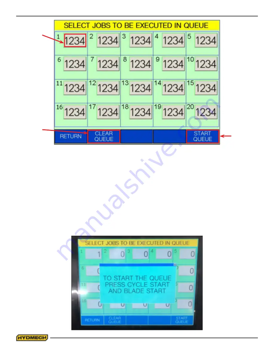
Step 7.   To ensure that no jobs from the previous queue have been programmed into this queue. It is recommended 

that the previous job queue be cleared before programming the new job queue. This is done by selecting the “CLEAR 

QUEUE” key on the touch screen. All job numbers currently inputted in the queue will disappear and the 20 grey input 

fields in the job queue should be set to their default setting of “0” meaning no job has been inputted.

Step 8.   Select grey input box on the 1st queue block on the interface, a number pad display window will appear over the 
job queue window. Key in the desired Job # from 1 to 1000 on the touch screen and press enter. The number pad display 
window will disappear and the desired job # will be displayed in the selected queue block on the job queue window. The 
purpose of a QUEUE is to allow the operator to run several jobs (maximum of 20) in series if they are of the same mate-
rial and shape. Order of the queue is determined by the number in each queue block. With the job programmed in queue 

block 1 being run first and the job programmed in queue block 20 being run last. 

Step 9.   After all jobs have been entered, select the “START QUEUE” key on the interface. The job queue window will dis

-

appear and a display window will prompt to initiate the job queue by pressing cycle start on the keypad. Press the “Cycle 

Start” button on the keypad to initiate the job queue.

Содержание V18APC

Страница 1: ...uture reference in a known location and easily accessible to all users of the device HYD MECH offers a great variety of options components and features for its various models Therefore some of the equipment described in this manual various illustrations and drawings may not be applicable to your particular machine The information and specifications provided in this manual were accurate at the time...

Страница 2: ...2 ...

Страница 3: ... BLADE TENSION CHECK 1 12 EARTH GROUNDING PROCEDURE 1 12 SECTION 2 OPERATING INSTRUCTIONS INTERFACE OPERATION INSTRUCTIONS 2 1 PUSH BUTTON DESCRIPTIONS 2 2 CONTROL SYSTEM OPERATING INSTRUCTIONS 2 4 MACHINE START UP 2 4 MANUAL MODE 2 5 KERF CORRECTION FOR ANGLE CUTTING MANUAL MODE 2 6 PARAMETERS 2 7 AUTOMATIC OPERATION 2 10 PROCEDURE FOR EDITING OR STARTING A NEW JOB IN AUTO MODE SIMPLE SHAPES 2 10...

Страница 4: ...TRICAL 4 1 SECTION 4 ELECTRICAL FOR ELEC SCHEMATICS AND COMPONENTS PARTS LIST SEE PDF ON ATTACHED CD 4 8 SECTION 5 HYDRAULIC SYSTEM HYDRAULIC PARTS LIST 5 1 GLAND ASSEMBLIES 5 2 PISTON ASSEMBLIES 5 2 HYDRAULIC SCHEMATIC AND PLUMBING DIAGRAM 5 3 SEE PDF ON ATTACHED CD 5 3 SECTION 6 MECHANICAL ASSEMBLIES MECHANICAL ASSEMBLY DRAWINGS PARTS LIST SEE PDF ON ATTACHED CD 6 1 SECTION 7 OPTIONS OPTIONAL AS...

Страница 5: ... Materials are within designed specifications and are non hazardous Owner is responsible to Keep Manual accessible at the machine Ensure only reliable fully trained personnel work with the machine Clearly define responsibilities of all personnel working with the machine Keep the machine in good working order Operator and Maintenance Personnel are responsible to Keep all safety equipment in order c...

Страница 6: ...azards associated with what you are doing That should get your brain working again Certainly production is important but if you think you re too busy to put safety first think how much production you ll lose if you get hurt You owe it to yourself your family and your co workers to PUT SAFETY FIRST Mandatory Information All persons operating this machine must have read and understood all of the fol...

Страница 7: ...nnot accept any liability for personal injury or property damage due to operator errors or non compliance with the Safety and Operating Instructions contained in this Manual RESPONSIBILITIES OF THE OWNER Organization of work This Operation and Maintenance Manual must always be kept near the machine so that it is accessible to all concerned The general statutory and other legal regulations on accid...

Страница 8: ...t on the machine must be checked At the start of every shift After maintenance and repair work When starting for the first time and after prolonged shutdowns Emergency Stop Button E Stops Always be aware of the location of the Emergency Stop Button s Do not allow material or objects to block your access to an Emergency Stop Damage If any changes capable of impairing safety are observed in the mach...

Страница 9: ... and duration of noise emission requiring hearing protection depends upon the national regulations in the country in which the machine is being used The actual level of noise emission by band sawing machines depends upon work piece size shape and material blade type blade speed and feed rate The only practical course of action is to measure the actual noise emission levels for the type of work tha...

Страница 10: ...onal injury or death All supervisors operators and maintenance personnel must locate and understand the safety information associated with each hazard label prior to operating or servicing the machine The safety hazard labels shown below are located at various positions on the machine to indicate possible safety hazards The location and re order part number of all the safety labels associated with...

Страница 11: ...Keep hands clear of vises and work piece when vises are opened or closed Be aware that vise closing or opening may result in potentially dangerous work piece movement Be aware also that the opening motion of a vise may create potential pinch points MOVING PARTS CAN CRUSH AND CUT Keep hands clear of chip auger Lock out power in accordance with your com pany s lock out procedures before attempting t...

Страница 12: ...ded while the blade is running and the V18 APC should not be operated unless all guards covers and doors are in place and closed Long and heavy stock should be supported where it extends off the saw table The operator should keep a safe distance from all moving parts especially the blade and operating vises Long hair loose clothing or gloves should not be worn while operating the V18 APC The area ...

Страница 13: ...pping weight of the V18 APC main machine is 6000 lb The machine can be lifted from the infeed side of the ma chine by forklift as shown below NOTE The head restraint plate attached to the head and table must be removed before machine start up ...

Страница 14: ...pack compartment Using a machinist s level level the saw from side to side and from front to back 0 1 0 22 8 54 7 72 5 90 5 82 1 102 2 0 3 5 73 4 70 5 6 5 5 7 45 5 46 0 80 2 85 0 B SECTION A A FOUNDATION MOUNTING LAYOUT 2 4 3 5 8 7 6 G F E D C B A H I A 3 00 6 00 1 25 75 THRU ALL 66 THRU ALL 3 4 10 UNC THRU ALL DETAIL B SCALE 1 8 2 1 4 3 5 8 7 6 I J K L M SCALE SHEET REV DRAWING NUMBER WOODSTOCK O...

Страница 15: ...led for shipping purposes to secure the head to the base Replace the two 5 16 NC countersunk screws which fasten the wear strip down INSTALLATION OF THE INFEED BASE The shipping weight of the infeed is 3000 lb The infeed can be lifted from the datum side by forklift as shown below ...

Страница 16: ...1 5 Move the infeed base into position under the wear plate and line up the holes for the roll pins Wear Plate Roll Pins Install the coolant side shields to both the infeed and outfeed side of the base ...

Страница 17: ...s 390715 to mate the two pieces together Level the infeed base with the machine by elevating the rear adjusting bolt Once level has been achieved make sure that all levelling bolts are touching the floor Remove the infeed base cover Feed the bundle of hydraulic hosed and electrical cables from inside the machine to the infeed base ...

Страница 18: ...Hydraulic Plumbing Diagram found in the DWG package CD NOTE LH Infeed configuration shown 91B 101A 61E 91C 62E 102A 92C 93 101 61B 91 62B 102 92 92B 92D Fasten the conduit to the bracket with the provided nut Connect the M12 connectors C 19 C 19 1 C2 23 C 23 C E1 C E2 ...

Страница 19: ... 8 SHUTTLE GUARD INSTALLATION Refer to the Perimeter Guard Assembly drawings in the DWG package CD Assemble the moveable side leg to the infeed assembly Assemble the datum side leg to the infeed assembly ...

Страница 20: ...rd and the hinged guard to the legs A pulley is mounted on a bracket and attached to each rear corner of the safety guard Fasten the three sides of the guard together at these brackets Adjust the levelling bolts on each leg to ensure the guard is level Remove the cover of the trip wire control box ...

Страница 21: ...ide rail Attach the other end of the wire rope to the eyebolt of the trip wire control box Adjust the turnbuckle to place enough tension on the wire rope to have the switch in the neutral position NOTE The switch can not be activated if there is not enough tension on the wire rope To reset the switch Tension the wire rope to pull the switch out of neutral and then press the reset button Attach the...

Страница 22: ...e necessary power hook up needs to be performed In order to provide safe operation as well as to prevent potential damage to the machine only qualified personnel should make the connections BEFORE START UP THE FOLLOWING TWO POINTS SHOULD BE CHECKED 1 Signs of damage that may have occurred during shipping to the electrical cables and the hydraulic hoses 2 The hydraulic oil level is between the uppe...

Страница 23: ...er entrance ground terminal where internal ground conductors should originate and connect to DIN terminal strip control transformer and the lid of control enclosure Also PLC and Interface units should have their own ground conductors connected to one of the main ground terminals Properly functioning ground system will Provide safety for personnel Ensure correct operation of electrical electronic d...

Страница 24: ... be pressed to activate the interface which will also start the hydraulic system Now all of the control keys have been activated and each key has an LED to indicate which functions are active In MANUAL MODE the operator has the ability to execute a single cut utilizing a pre programmed SINGLE CUT MODE In AUTOMATIC MODE the PLC has the capacity to program and store 1000 jobs Designated job numbers ...

Страница 25: ...huttle to the back away from the blade and will stop and hold its position if the key is released SHUTTLE SLOW FAST Pressing this key will cause the shuttle to move either fast or slow The red LED indicates that the shuttle will move FAST Pressing the key will switch this function back to SLOW INFEED VISE OPEN Pressing this key will open the infeed vise and will stop and hold its position if the k...

Страница 26: ...TO MODE the FIXED VISE must be activated SERVICE MODE The SERVICE MODE allows the user to adjust the various PLC parameters The user will be prompted for a password Contact Hyd Mech Group Limited to access this mode LASER ON OFF Pressing this key will cause the LASER to turn on or off The red LED indicates that the LASER will be on MACHINE START Pressing this key will activate the control panel di...

Страница 27: ...oom button There is a short delay to allow the machine software to load Press the machine start button to start the hydraulics If the head is not at 90 degrees then the display screen will look as follows CONTROL SYSTEM OPERATING INSTRUCTIONS OPTIONAL EQUIPMENT SHOWN ...

Страница 28: ...abled when in MANUAL MODE The screen should look as follows To program the required angle press Angle Go To The screen will change to the picture below To enter the required angle touch the screen at the angle numerical values The number pad display window will open Enter a numerical angle then press the ent button Left or Right is changed by toggling L or R on the display Press the CYCLE START bu...

Страница 29: ...th must be set longer than the desired length by an amount called the KERF CORRECTION or the kerf value must be adjusted This is due to the fact that the PLC will not account for a difference in the kerf value at various angles If the kerf value is to be adjusted its value can be accessed by pushing the next button To return to previous screen press exit key The Standard kerf and corrected values ...

Страница 30: ...cut and continue moving forward until it exits the material Shuttle will move the stock forward by the distance set in the BLADE CHAMBER PUSH DISTANCE parameter and will push away the cut pieces Shuttle will move back allowing the head to retract Head will retract Shuttle will feed the next length to cut The cycle will repeat 6 BLADE CHAMBER PUSH DISTANCE This parameter defines the distance that t...

Страница 31: ...arameters can be viewed but a password will be needed to change any settings See PLC Parameters at the end of this section to view the list HYD MECH service department should be contacted before attempting to change any of these settings ...

Страница 32: ...T WINDOW Allowable tolerance from programmed angle HEAD SWING ACEL DECEL DISTANCE Acceleration Deceleration distance HEAD SWING MAX SPEED Head swing maximum speed HEAD SWING SOFT 30 DEG L Head swing soft over travel HEAD SWING SOFT 30 DEG R Head swing soft over travel HEAD 90DEG SET Set new 90 deg position BP RADIUS The distance in inches from the front side of the blade to the pivot point of the ...

Страница 33: ...tted value in the top field highlighted in yellow Select the CLEAR JOB option on the touch screen to clear all the previous job properties It is important to note that the current job being edited is always the job indicated in the yellow highlighted field AUTOMATIC OPERATION To enter AUTO MODE the Infeed Vise must be in the closed position When the AUTO MODE push button is pressed the red indicat...

Страница 34: ...window will appear over the job display window Key in the desired quantity from 1 to 999 on the touch screen and press enter The number pad display window will disappear and the quantity required on the job display window will be adjusted to the desired value Step 5 After the quantity has been assigned The number of pieces cut must be assigned This is done by selecting the grey input box under QUA...

Страница 35: ... the desired Job from 1 to 1000 on the touch screen and press enter The number pad display window will disappear and the desired job will be displayed in the selected queue block on the job queue window The purpose of a QUEUE is to allow the operator to run several jobs maximum of 20 in series if they are of the same mate rial and shape Order of the queue is determined by the number in each queue ...

Страница 36: ...d rate be lowered or stopped to allow for adjustments in the blade speed before increasing the feed rate for the first cut Step 11 To increase the blade speed press and hold the Blade Speed button until the desired speed is displayed on the touchscreen To decrease the blade speed press and hold the Blade Speed button until the desired speed is dis played on the touchscreen These buttons are locate...

Страница 37: ...ckwise rotation to increase and clockwise rotation to decrease Fast Approach Lever Depress for fast head approach Feed Rate Knob Used to control the speed of head advancement S25 9 25B 392540 29 50 6 75 STEP4DETERMINE OPTIMUM BLADE SPEED V ft min STEP DETERMINE FEED RATE SETTING FR in min 5 1 STEP DETERMINE EFFECTIVE MATERIAL WIDTH W in SET FEED FORCE LIMIT SET FEED FORCE TO MATERIAL SECTION TYPE ...

Страница 38: ... and it is used in STEPS 3 and 4 In Example 1 for an 8 200 mm diameter solid Effective Material Width is 8 200mm STEP 2 SET FEED FORCE LIMIT The Feed Force Limit is the maximum amount of force with which the head is allowed to push the blade into the work piece FEED FORCE LIMIT should be set with the head in the down mode according to the label CUTTING SOLIDS For cutting solids the wider the secti...

Страница 39: ...ciently Too fine a blade must be fed slower on wide mate rial because the small gullets between the teeth will get packed with chips before they get across and out of the cut Too coarse a blade must be fed slower because it has fewer teeth cutting and there is a limit to the depth of a cut taken by each tooth Allowance for the use of a non optimum blade is made in STEP 5 In our Example 1 Effective...

Страница 40: ...he point where a vertical line from 8 200mm intersects the Medium Carbon Steel Curve From this intersection point run horizontally left to the vertical axis optimum blade speed axis and find the point marked 200 For 8 200mm diameter 1045 Carbon Steel solid bar 200 ft min 60m min is the optimum blade speed NOTE Higher than optimum blade speed will cause rapid blade dulling Lower than optimum blade ...

Страница 41: ...the following way On the horizontal axis blade speed axis find 200 ft min 60mm min Find the point where a vertical line from 200 ft min 60mm min would intersect the 2 3 blade pitch curve From this intersection point run horizontally left to the vertical FEED RATE axis to arrive at 1 8 in min 45mm min FEED RATE Thus 1 8 in min 45mm min is the FEED RATE for cutting 8 200mm diameter 1045 Carbon Steel...

Страница 42: ...or 225 ft min X 60 135 ft min 70 m min x 60 42 m min STEP 5 Feed Rate for 3 4 TPI blade 1 8 in min 45 mm min Feed Rate for 4 6 TPI blade 1 8 in min X 70 1 3 in min reduced by finer than optimum blade pitch factor 45 mm min x 70 31 5 mm min EXAMPLE 3 MaterialBundle Low carbon steel 2 x 2 Tube with 1 4 wall 12 piece bundle 50 mm x 50 mm with 6 mm wall Dimensions 6 x 8 150 mm x 200 mm STEP I Effectiv...

Страница 43: ...an be limited and thereby reduce the cycle time for each cut The head back limit handle is located on the control mounting arm It can be pulled out full back position or pushed in With the handle pulled fully out fully retract the head Load and close the vise on the material advance the head so the blade is approximately 1 4 from the material at its widest point Push the handle fully in retract th...

Страница 44: ...earance between the brake plate 1 and the rear brake pad 5 is 005 010 Lock the jam nut 2 Make sure the two roll pins 7 secure the brake pads from rotation Swing the head in both directions through the entire range to make sure the brake is working properly Re install the brake cover BRAKE COVER CLEARANCE 010 MAX 1 Brake plate V18 272 01 2 Lock Nut 3 Brake Nut 4 Front Brake Pad V18 271 01B 5 Rear B...

Страница 45: ... such starting shall be taken LOCK OUT PROCEDURE Whenever work is to be performed on a machine the following steps shall be taken 1 Operator shuts down the machine The head should be swung to 30o left or right before any hydraulic service is performed to prevent the head from moving unexpectedly 2 The person in charge should follow Lockout procedures as is required by his organization The main pow...

Страница 46: ...er clockwise The top carbide lever is shown in the photo The bottom lock lever is on the lower guide arm 5 Turn the Blade Tension Switch from the TIGHTEN position RUN through central HOLD position and briefly to the LOOSEN position By jogging the switch between hold and loosen it is possible to regulate the degree of looseness of the blade It is helpful to have the blade just loose enough that it ...

Страница 47: ...to the OFF position 13 Blade change procedure is complete BLADE TRACKING First inspect the blade wheels for wear or damage and repair as required Blade tracking adjustment should always begin at the wheel where the tracking is farthest out of specification Using the instructions below adjust the worst wheel jog the blade and check both wheels Repeat this process until both wheels are within specif...

Страница 48: ...n the adjust ing set screw B clockwise until tight and then loosen it 1 8th of a turn With the lever still in the locked position tighten the small set screw in the side of the lever This should put just enough pressure on the blade to permit you to push the blade out approximately 1 8 In the event that the pads must be replaced refer to the exploded parts drawing in Section 6 Idler wheel tracking...

Страница 49: ...ICATION V18 WITH A412 GEARBOX The Bonfiglioli A412 gearbox used on the V18 is supplied with 5 0 litres 1 32 US gallon of Mobil SHC 630 synthetic oil This oil has an ISO Viscosity Grade of 220 that is optimum for ambient temperatures from 10 40 Deg C 70 104 Deg F If the machine will be operated for prolonged periods at ambient temperatures below 20 Deg C 70 Deg F an oil of ISO Viscosity Grade 150 s...

Страница 50: ... grease nipples Anti tip roller X2 Bearing Block X4 Vise Ways X2 One of 4 linear bearing block grease nipples There is one at each corner of the head carrier cover Remove round plas tic plugs to gain access to the two back grease nipples PLUG ...

Страница 51: ...n will be very low and it should be unnecessary to add oil more often than at filter changes Add oil only to the top line on level gauge The hydraulic tank capacity is 8 US gallons NOTE The V18 APC is shipped from the factory with Texaco Rando HD 46 oil Generally any brand of recognized mineral hy draulic oil with the same properties should be compatible with Texaco Rando HD 46 oil but to avoid an...

Страница 52: ... output fails the coil may be bad Check dirt in valve spool 4 An operator control will not respond 4 The switch or pushbutton contact assembly is defective 4 Replace the component that is inoperative Test voltage levels at switch 5 Hydraulics run but blade will not start 5a Check for red fault light at VFD 5a Interrupt main supply to machine for two to three minutes 5b Red fault light on VFD is no...

Страница 53: ...ension is determined by system pressure Check 6 Tooth strippage 6a Blade pitch is too fine 6a Select a blade with a coarser pitch for cutting 6b Blade brush is not cleaning 6b Replace or adjust the blade brush 6c Excessive feed rate 6c Reduce the feed rate Check calculations for rate 6d Excessive feed force 6d Reduce the feed force pressure maximum setting 7 No coolant flow 7a Coolant reservoir lo...

Страница 54: ...d on din rails The illustration below shows the location of the Din rails with the installed components and the des ignated TB number The following pages will show and explain in brief how to understand the correlation between the electrical schematic and the control panel with regards to TB1 to TB6 TB1 TB2 TB3 TB6 TB5 SECTION 4 ELECTRICAL ...

Страница 55: ...C and terminals mounted to it For example if the electrical schematic shows a terminal described as TB1 2 This indicates that the terminal is located on din rail TB1 and is terminal 2 TB1 5 This would indicate that the terminal is mounted on TB1 and is terminal 5 TB1 5 TB1 2 ...

Страница 56: ...TB2 in the control panel For example if the electrical schematic shows a terminal described as TB2 3 This indicates that the terminal is located on din rail TB2 and is terminal 3 TB2 6 This would indicate that the terminal is mounted on TB2 and is terminal 6 TB2 3 TB2 6 ...

Страница 57: ... the electrical schematic shows a terminal described as TB3 7 This indicates that the terminal is located on din rail TB3 and is terminal 7 TB3 16 This would indicate that the terminal is mounted on TB3 and is terminal 16 TB4 TB4 is located in another control panel and will be included on page 7 TB3 7 TB3 16 ...

Страница 58: ...4 5 TB5 TB5 contains fusible terminals and a power supply These are identified on the schematic as FU3 to FU8 and PWS for the power supply ...

Страница 59: ...ontains ground terminals partially visible mounted either side of the contactors MS1M MS2M and are indicated on the schematic as TB6 TB6 1 2 The mounting location in the control panel is shown on page 1 TB6 1 TB6 2 ...

Страница 60: ...I panel Human Machine Interface This houses the selector switches and push buttons As in the main panel the same concept applies for example TB4 25 This indicates that the terminal is located on din rail TB4 and is terminal 25 TB4 25 ...

Страница 61: ... which are 1 Page This refers to the current page number 2 Pg This refers to the total number of pages in the entire project and is for internal HYD MECH use only On each Page there are a row of 4 digit numbers on the left of the page For example Page 14 shows the numbers from 1400 to 1439 The first 2 digits refer to the page number which in this case is page 14 The latter 2 digits refer to the ro...

Страница 62: ...DF5 0 00 11 808424 Block Manifold 6 Position MB6PA 12 808422 Block Manifold 2 Position MB2P_B 13 363160 Valve Cartridge PV2P A C 14 363155 Valve Cartridge PRV2 10 S 0 20 15 363160 Valve Cartridge PV2P A C 16 363145 Valve Cartridge Prv1 With Body PRV1 10 K 6T 6 17 363185 Valve Directional DG4V 3S 2A MUB5 60 18 363295 Valve Sandwich DCV3P AB T 19 363290 Valve Sandwich DCV3P AB C 20 363300 Valve Sand...

Страница 63: ...A 362835 363340 4 0 363005 362805 CS40 GL 01A 362840 363345 5 0 363015 362810 CS50 GL 01A 362840 363345 CYLINDER DIAMETER A TEFLON RING B LOADER RING C PISTON D O RING 2 0 363035 362950 CS20 PS 01B 362905 2 5 363040 362965 CS25 PS 01 362910 3 0 363045 362980 CS30 PS 01 362910 3 5 363050 362990 CS35 PS 01 362925 4 0 363055 363000 CS40 PS 01 362940 5 0 363060 363010 CS50 PS 01 362940 CYLINDER ASSEMB...

Страница 64: ...5 3 HYDRAULIC SCHEMATIC AND PLUMBING DIAGRAM SEE PDF ON ATTACHED CD ...

Страница 65: ...6 1 MECHANICAL ASSEMBLY DRAWINGS PARTS LIST SEE PDF ON ATTACHED CD SECTION 6 MECHANICAL ASSEMBLIES ...

Страница 66: ...7 1 SECTION 7 OPTIONS OPTIONAL ASSEMBLY DRAWINGS SEE PDF ON ATTACHED CD ...

Страница 67: ... 118 m min Blade Guides carbide inserts Blade Wheel Dia 19 483mm Motors blade drive 7 1 2 HP 5 6 KW hydraulic pump drive 2 HP 1 5 KW Pumps Hydraulic 6 1 2 U S Gal min 25 Liters min Coolant 3 1 2 U S Gal min 13 Liters min Vises hydraulic full stroke Head Swing hydraulically positioned and locked full 60º left or right Table Height 44 1117mm Feed System variable pressure 0 300 PSI 0 2068 kPa variabl...

Страница 68: ...OSE IT TO OTHERS FOR ANY PURPOSE WHATSOEVER ALL RIGHTS RESERVED A 0 B C D E G F H I J K L M 2 1 4 3 5 8 7 6 2 1 4 3 5 8 7 6 G F E D C B A H I J K L M 0 ECN NUMBER REV DATE BY REVISIONS STANDARD HYDMECH TOLERANCES UNLESS OTHERWISE SPCIFIED DIMENSIONS ARE IN INCHES THIRD ANGLE PROJECTION TITLE DRWN BY CHKED BY MAT L DATE SCALE SHEET REV DRAWING NUMBER WOODSTOCK ONTARIO CANADA N4S 0A9 HYDMECH GROUP L...

Страница 69: ... REPRODUCTION PUBLICATION OR DISTRIBUTION OF ANY PART REQUIRES WRITTEN CONSENT OF HYD MECH GROUP THIS DATA IS THE PROPERTY OF HYD MECH GROUP AND ITS POSSESION CONFERS NO LICENSE TO USE OR RIGHT OR LICENSE TO DISCLOSE IT TO OTHERS FOR ANY PURPOSE WHATSOEVER ALL RIGHTS RESERVED A 0 B C D E G F H I J K L M 2 1 4 3 5 8 7 6 2 1 4 3 5 8 7 6 G F E D C B A H I J K L M 0 SCALE SHEET REV DRAWING NUMBER WOOD...

Страница 70: ...Y PURPOSE WHATSOEVER ALL RIGHTS RESERVED A 0 B C D E G F H I J K L M 2 1 4 3 5 8 7 6 2 1 4 3 5 8 7 6 G F E D C B A H I J K L M 0 ECN NUMBER REV DATE BY REVISIONS STANDARD HYDMECH TOLERANCES UNLESS OTHERWISE SPCIFIED DIMENSIONS ARE IN INCHES THIRD ANGLE PROJECTION TITLE DRWN BY CHKED BY MAT L DATE SCALE SHEET REV DRAWING NUMBER WOODSTOCK ONTARIO CANADA N4S 0A9 HYDMECH GROUP LIMITED 50002273 MO Apr ...

Страница 71: ...ENTIAL REPRODUCTION PUBLICATION OR DISTRIBUTION OF ANY PART REQUIRES WRITTEN CONSENT OF HYD MECH GROUP THIS DATA IS THE PROPERTY OF HYD MECH GROUP AND ITS POSSESION CONFERS NO LICENSE TO USE OR RIGHT OR LICENSE TO DISCLOSE IT TO OTHERS FOR ANY PURPOSE WHATSOEVER ALL RIGHTS RESERVED A 0 B C D E G F H I J K L M 2 1 4 3 5 8 7 6 2 1 4 3 5 8 7 6 G F E D C B A H I J K L M 0 SCALE SHEET REV DRAWING NUMBE...

Страница 72: ...er items used in the manufacture of the V18APC but not originally manufactured by Hyd Mech are subject to the original manufacturer s war ranty Hyd Mech will provide such assistance and information as is necessary and available to facilitate the user s claim to such other manufacturer Liability or obligation on the part of Hyd Mech for damages whether general special or for negligence and expressl...

Страница 73: ......

Отзывы: