


19 / 27
Table 2. (Input table)
Point
Level (Source column)
Volume (Output column)
Note: The level can be measured effectively between 0.20 m (0.66 ft) and 5.60 m (18.5 ft).
When the level of the measured material falls below the end of the measuring probe, the device
will still indicate 0.20 m, because the level meter can only display between 0.20 m (0.66 ft) and
5.60 m (18.5 ft) according to the probe length (which is now 5.8 m [19 ft]).
The size of the dead zone depends on the equipment and the type of probe.
1
0.0 m (0.0 ft)
0.0 m³ (0.0 ft³)
2
0.20 m (0.66 ft)
0.5 m³ (17.65 ft³)
3
0.75 m (2.5 ft)
1.0 m³ (35 ft³)
4
1.00 m (3.3 ft)
1.5 m³ (52.9 ft³)
5
5.60 m (18.5 ft)
16.8 m³ (593.3 ft³)
Additional procedure for
displaying 4… 20 mA current output
(using HyView)
Step
Operation
Entered data / Selected value
1
Go to “Outputs” and set “Current generator mode” to “Auto” (default)
Auto
2
Set the error status to the appropriate mode in “Error indication …”
(default).
Hold
3
Select the “Assignment of 4 mA
-
PV (P10)” field and enter the min. volume value for the 4 mA output current.
0.5 m³ (17.65 feet³)
4
Go to the “Assignment of 20 mA–
PV (P11)” field and enter the max. 20 mA output current value
.
16.8 m³ (593.3 feet³)
5
Press the button labeled “Send” in the lower right row of the window to load the new values into the device
6
Press the “X” close button to exit the device settings window
.
5.2.
P
ROGRAMMING WITH THE
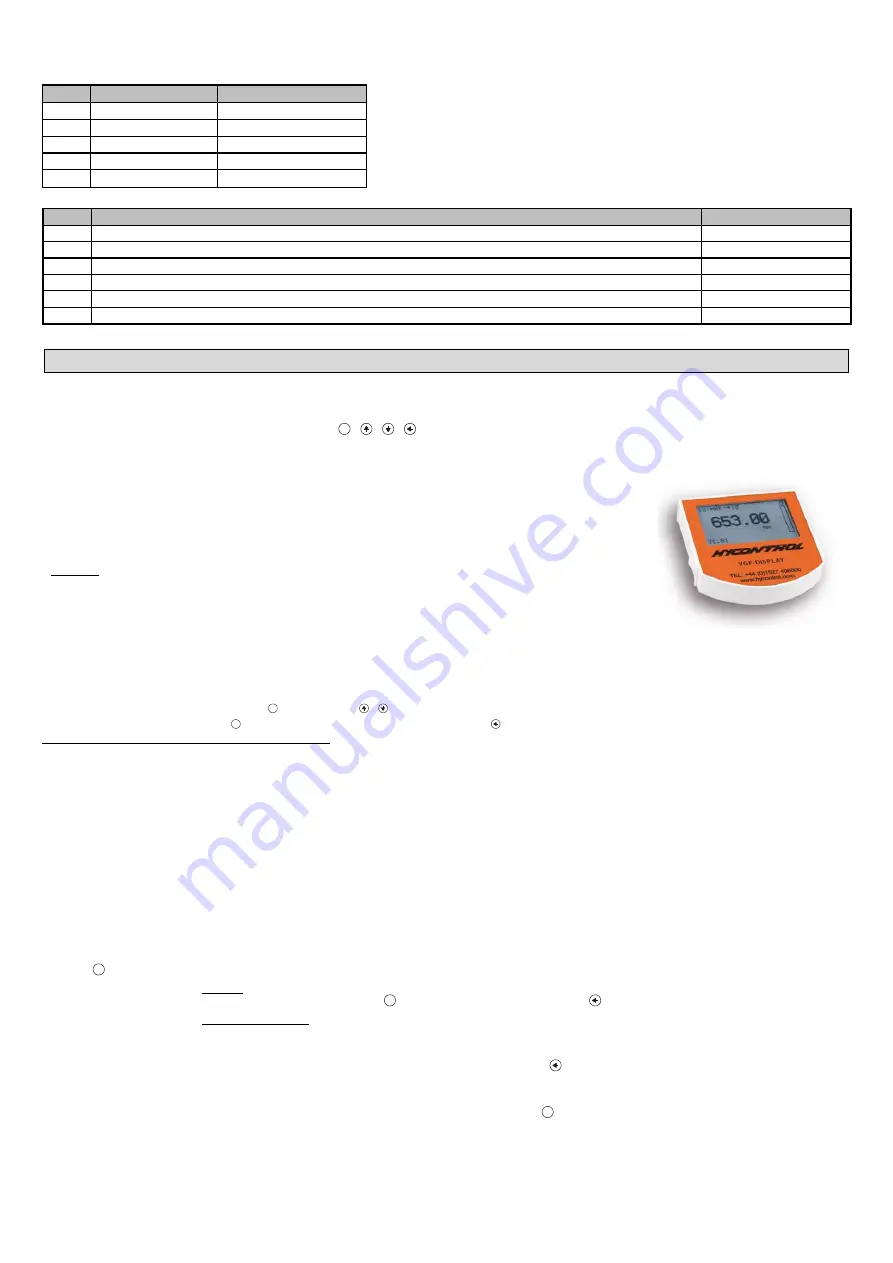
VGF-DISPLAY:
D
ISPLAY
U
NIT
The most important parameters of VF05 can also be set with the VGF-DISPLAY: display unit.
By default, the display shows the primary measurement result (from which the output current is calculated).
In addition to the measured value displayed in large numbers, a bar graph representing the value of the output current is also shown on the right.
Programming is done using a text menu. You can use the
E
/ / / buttons to navigate the menu.
5.2.1.
VGF-DISPLAY: Display Unit
Display
64 × 128 dot matrix LCD, signs, units and bar graph
Ambient temperature
–20…+60 °C
(
–
4
…+
140 °F)
Housing material
PBT fiberglass, plastic (DuPont
)
The plug-in module containing the VGF-DISPLAY: LCD display (universal - can also be used in other HYCONTROL
devices, provided the device software supports VGF-DISPLAY:).
Warning!
The VGF-DISPLAY: uses an LCD, do not expose the VGF-DISPLAY: to prolonged exposure to strong heat or sunlight as
the display may be damaged.
If the VF05 cannot be protected against solar radiation not possible or it is used outside the operating temperature
range of the VGF-DISPLAY:, do not leave the VGF-DISPLAY: in the VF05!
5.2.2.
The Behavior of the VF05 while Programmed Manually
By default, VF05 displays the main measurement data on the VGF-DISPLAY: display (hereafter referred to as display).
Enter the programming menu by pressing the
E
button. Use the / buttons to navigate through the menu items.
Enter the selected menu item with the
E
button. Return to the previous menu level with the key.
The buttons only work if the VGF-DISPLAY: is present!
The device continues measuring while the menu is accessed. Changes made in the menu take effect when you exit the menu.
If you do not exit the VF05 menu, the device will automatically return to the measurement display state after 30 minutes. In this case, any changes made in the menu
will be ignored.
If the VGF-DISPLAY: is pulled out of the VF05, the VF05 will automatically exit the menu and ignore any changes made in the menu.
Since programming with VGF-DISPLAY (manual programming) and remote programming on HART (REMOTE MODE) create a conflict, only one mode can be used
at a time.
Manual programming has priority overt HART!
During manual programming,
the device sends a “device is busy” signal to the HART master (HART Response code: 32 –
Device is busy).
In remote programming mode,
REM
is displayed on the top right of the display. In this case, manual programming of the device is disabled, the menu cannot be
accessed.
If no VGF-DISPLAY: is connected, the LEDs will be visible, the flashes of the COM LED will indicate HART communication, and the VALID LED will indicate if the
data measured by the device is valid.
5.2.3.
Manual Programming
Press the
E
button to modify the parameter under the cursor in the submenu.
There are two modes:
Text list:
Navigated is same as in the menu.
The
E
button executes the selection, and the button cancels it.
Editable number field:
Serves to edit numeric values.
Editing is aided by an (inverted) cursor.
The number under the cursor can be changed with the / buttons (no overflow).
The cursor can be moved left with the arrow (max. 9 character-positions, including the decimal
point).
When the end of the field is reached, the cursor returns to the first position on the right.
Editing is concluded by pressing the
E
button.
In this case, VF05
will check the entered value and if it is not correct, “WRONG VALUE!” is
displayed in the bottom row.


