ZX7-315/400/500/630IGBT OPERATOR’S MANUAL
- 7 -
4. Hardware Overview
This machine including: shell, inner part, handle and base, while the inner part include: cooling fan, main
transformer, IGBT modules, filter reactor, fast recovery diode modules and PCBs etc.
5. General Description
5.1 Working theory
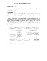
ZX7–IGBT series welding machine adopts IGBT as the main circuit switch. The three-phase AC input
power inverted to 20KHz HF current through the rectify of the full bridge. While after the depression of the
HF transformer, rectified by the FRD and filtered by the reactor, the HF current will change to the
low-voltage but high welding current..
The control circuit will control the output current through the adjusting of the pulse width. The negative
feedback signal, which is the real welding current get from the output current sensor, put into the special
PWM circuit after compared with the current adjust signal, then output the driving pulse to control the
IGBT, so that the output current will keep stable to get descending external characteristic.
Force current function: the control circuit will increase the current when the welding voltage less than
15V, so that the electrode will not stick with the workpiece to enlarge the arc penetration.
5.2 Principal diagram
5.3 Welding machine output CC/CV feature diagram
Содержание ZX7-315IGBT
Страница 12: ...ZX7 315 400 500 630IGBT OPERATOR S MANUAL 12 ...


