


8
CHECK INLET GAS PRESSURE
UNIT DAMAGE HAZARD
Failure to follow this caution may result in unit damage.
DO NOT operate furnace more than one minute to check
inlet gas pressure, as conversion is not complete at this time.
CAUTION
!
NOTE
: This kit is to be used only when inlet gas pressure is
between 4.5--in. W.C. and 13.6--in. W.C.
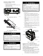
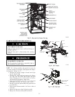
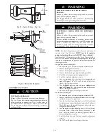
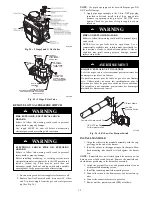
1. Verify manometer is connected to inlet pressure tap on gas
valve. See Fig. 8.
2. Turn on furnace power supply.
3. Turn gas supply manual shutoff valve to ON position.
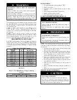
FIRE, EXPLOSION, ELECTRICAL SHOCK
HAZARD
Failure to follow this warning could result in personal
injury, death or property damage.
Gas supply MUST be shut off before disconnecting
electrical power and proceeding with conversion.
!
WARNING
ELECTRICAL SHOCK, FIRE OR EXPLOSION
HAZARD
Failure to follow this warning could result in personal
injury, death or property damage.
Before installing, modifying, or servicing system, main
electrical disconnect switch must be in the OFF position and
install a lockout tag. There may be more than one
disconnect switch. Lock out and tag switch with a suitable
warning label. Verify proper operation after servicing.
!
WARNING
4. Turn furnace gas valve switch to ON position.
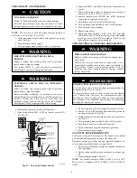
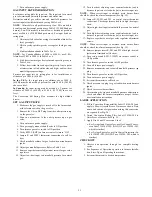
5. Turn Setup Switch SW1 (LHT) on furnace control ON
(see Fig. 11).
TEST / TWIN
HUM
PL
T
SEC-2
SEC-1
COM
24VAC
PL1
W2 Y
DHUM G COM W/W1 Y/Y2 R
24V
FUSE 3-AMP
EAC-2
EAC-1
L1
BL-1
PR-1
L2
COM
HI HT
COOL
LO HT
SPARE 2
24V MTR
TA
P
S
BLOWER SPEED
TERMINALS
115-VAC (L2)
NEUTRAL
CONNECTIONS
LED OPERATION
& DIAGNOSTIC LIGHT
3-AMP FUSE
24-V THERMOSTAT
TERMINALS
SET UP SWITCHES
LOW HEAT ONLY
AND BLOWER
OFF-DELAY
TWINNING AND/OR
COMPONENT TEST
TERMINAL
ACRDJ - AIR CONDITIONING
RELAY DISABLE JUMPER
HUMIDIFIER TERMINAL
(24 VAC 0.5 AMPS MAX)
TRANSFORMER
24 VAC CONNECTIONS
PL1-LOW VO LTAGE
MAIN HARNESS CONNEC TOR
PL2 - HOT SURFACE
IGNITER/INDUCE R
MOTOR CONNECTION
115 VAC
BLOWER POWER (BL1)
CONNECTION
115 VAC LINE (L1)
INPUT
LHT
OFF
DLY
ON
OFF
1 2 3
IDR
HSIR
IDM
IHI/L
OR
PL2
1
HSI HI LO
1
EAC TERMINAL
115 VAC 1.0 AMP MAX
115 VAC
TRANSFORMER
PRIMARY
SPARE 1
A11470
Fig. 11 -- Two--stage Furnace Control
6. Jumper R--W/W1 and R--W2 thermostat connections on
control.
7. When main burners ignite, confirm inlet gas pressure is
between 4.5--in. W.C. and 13.6--in. W.C.
8. Remove jumper across R--W/W1 and R--W2 thermostat
connections to terminate call for heat.
9. Turn furnace gas valve switch to OFF position.
10. Turn gas supply manual shutoff valve to OFF position.
11. Turn off furnace power supply.
12. Remove manometer.
13. Apply pipe dope sparingly to the 1/8-in. NPT pipe plug
and install in the 1/8-in. tapped inlet pressure tap opening
in the gas valve. DO NOT over--tighten. Check for gas
leaks after gas supply has been turned on.
CHECK FURNACE AND MAKE ADJUSTMENTS
FIRE AND EXPLOSION HAZARD
Failure to follow this warning could result in personal injury
and/or death.
NEVER test for gas leaks with an open flame. Use a
commercially available soap solution made specifically for
the detection of leaks to check all connections. A fire or
explosion may result causing property damage, personal
injury or loss of life.
!
WARNING
RISQUE D’EXPLOSION ET D’INCENDIE
Le fait de ne pas suivre cet avertissement pourrait entraîner des
dommages corporels et / ou la mort.
Ne jamais examiner pour les fuites de gaz avec une flamme
vive. Utilisez plutôt un savon fait specifiquement pour la
détection des fuites de gaz pour verifier tous les connections.
Un incendie ou une explosion peut entrainer des dommages
matériels, des blessures ou la mort.
!
AVERTISSEMENT
1. Be sure main gas and electric supplies to furnace are off.
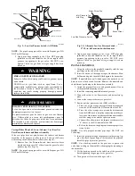
2. Remove 1/8-in. NPT pipe plug from manifold pressure tap
on downstream side of gas valve.
3. Attach manometer to manifold pressure tap on gas valve.
(see Fig. 8.)
4. Turn gas supply manual shutoff valve to ON position.
5. Turn furnace gas valve switch to ON position.
6. Check all threaded pipe connections for gas leaks.
7. Turn on furnace power supply.
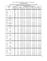
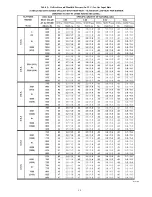
GAS INPUT RATE INFORMATION
See furnace rating plate for input rate. The input rate for natural
gas is determined by manifold pressure and orifice size.
Determine natural gas orifice size and manifold pressures for
correct input at installed altitude by using Table 3.
1. Obtain yearly heat--value average (at installed altitude) for
local gas supply.
2. Obtain yearly specific--gravity average for local gas sup-
ply.
3. Find installation altitude in Table 3.
NOTE
: For Canada altitudes of 2000 to 4500 ft. (610 to 1372
M), use U.S.A. Altitudes of 2001 to 3000 ft. (610 to 914 M) in
Table 3.
Содержание KGAPN43012SP
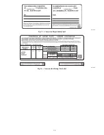
Страница 10: ...10 A11514 Fig 13 Conversion Responsibility Label A11515 Fig 14 Conversion Kit Rating Plate Label ...
Страница 14: ...14 Table 5 Orifice Size and Manifold Pressure In W C for Gas Input Rate A10184 ...
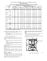
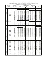
Страница 15: ...15 Table 5 Orifice Size and Manifold Pressure In W C for Gas Input Rate cont A10184A ...
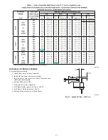
Страница 16: ...16 Table 6 Orifice Size and Manifold Pressure In W C for Gas Input Rate A10185 ...


