12
A03059
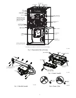
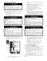
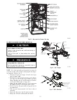
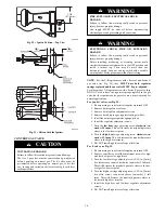
Fig. 15 -- Representative Furnace Drawing
MANIFOLD/ORIFICE/BURNER REMOVAL
UNIT OPERATION HAZARD
Failure to follow this caution may result in unit damage or
improper operation.
Label all wires prior to disconnection when servicing
controls.
CAUTION
!
D’EQUIPMENT D’OPERATION
Lors des opérations d’entretien des commandes, étiqueter
tous les fils avant de les déconnecter.
PRUDENCE
!
NOTE
: Use a back-up wrench on the gas valve to prevent the
valve from rotating on the manifold or damaging the mounting to
the burner box. See Fig. 16 & 17.
1. Disconnect the gas pipe from gas valve and remove pipe
from the furnace casing.
2. Disconnect the connector harness from gas valve Discon-
nect wires from Hot Surface Igniter (HSI) and Flame
Sensor. Disconnect the two wires from the Low Gas Pres-
sure Switch (LGPS) located on the gas valve.
3. Support the manifold and remove the 4 screws that secure
the manifold assembly to the burner box and set aside.
4. Note the location of the green/yellow wire ground wire for
re-assembly later.
5. Slide one--piece burner assembly out of slots on sides of
burner box.
6. Remove the flame sensor from the burner assembly.
7. Remove the orifices from the manifold and discard.
Attach Green/Yellow
ground wire here
Manifold Assy
Sensor Flame
Clip, Harness
Burner Assy
Burner Support Assy
Switch, Temp (2)
Ignitor
Bracket Ignitor
A11390
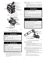
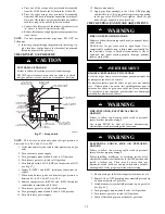
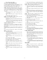
Fig. 16 -- 80% Burner
Gas Valve
Screw (2)
Attach Green/Yellow
ground wire here
Orifice
Manifold
A11395
Fig. 17 -- 80% Manifold
Содержание KGAPN43012SP
Страница 10: ...10 A11514 Fig 13 Conversion Responsibility Label A11515 Fig 14 Conversion Kit Rating Plate Label ...
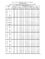
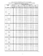
Страница 14: ...14 Table 5 Orifice Size and Manifold Pressure In W C for Gas Input Rate A10184 ...
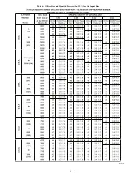
Страница 15: ...15 Table 5 Orifice Size and Manifold Pressure In W C for Gas Input Rate cont A10184A ...
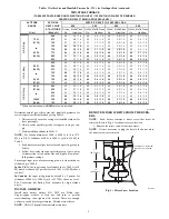
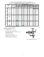
Страница 16: ...16 Table 6 Orifice Size and Manifold Pressure In W C for Gas Input Rate A10185 ...


