19
A05196
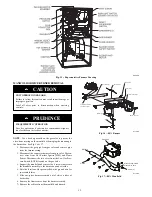
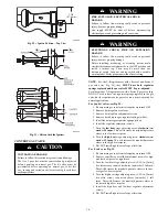
Fig. 24 -- 2 Stage J and G Gas Valves
ON
O
F
F
ON/OFF
SWITCH
INLET
PRESSURE
TAP
BURNER ENCLOSURE
REFERENCE PRESSURE TAP(2-STAGE
AND VARIABLE-SPEED, CONDENSING
FURNACES ONLY)
MANIFOLD
PRESSURE
TAP
LOW-HEAT
ADJUSTMENT
ALLEN SCREW
(UNDER CAP)
HIGH-HEAT
ADJUSTMENT
ALLEN SCREW
(UNDER CAP)
PLUG BUTTON
(2-STAGE AND
VARIABLE–SPEED,
NON–CONDENSING
FURNACES ONLY)
A01069
Fig. 25 -- 2 Stage E Gas Valve
REMOVE LOW GAS PRESSURE SWITCH
FIRE, EXPLOSION, ELECTRICAL SHOCK
HAZARD
Failure to follow this warning could result in personal
injury, death or property damage.
Gas supply MUST be shut off before disconnecting
electrical power and proceeding with conversion.
!
WARNING
ELECTRICAL SHOCK, FIRE OR EXPLOSION
HAZARD
Failure to follow this warning could result in personal
injury, death or property damage.
Before installing, modifying, or servicing system, main
electrical disconnect switch must be in the OFF position and
install a lockout tag. There may be more than one
disconnect switch. Lock out and tag switch with a suitable
warning label. Verify proper operation after servicing.
!
WARNING
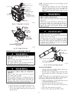
1. Be sure main gas and electric supplies to furnace are off.
2. Remove Low Gas Pressure Switch, brass street 90
_
elbow
and 2--in. brass nipple from the gas valve inlet pressure
tap. (See Fig. 26.)
NOTE
: Use pipe dope approved for use with Propane gas. DO
NOT use Teflon tape.
3. Apply pipe dope sparingly to the 1/8--in. NPT pipe plug
(provided in kit) and install in the 1/8--in. tapped inlet
pressure tap opening in the gas valve. DO NOT over--
tighten. Check for gas leaks after gas supply has been
turned on.
FIRE AND EXPLOSION HAZARD
Failure to follow this warning could result in personal injury
and/or death.
NEVER test for gas leaks with an open flame. Use a
commercially available soap solution made specifically for
the detection of leaks to check all connections. A fire or
explosion may result causing property damage, personal
injury or loss of life.
!
WARNING
RISQUE D’EXPLOSION ET D’INCENDIE
Le fait de ne pas suivre cet avertissement pourrait entraîner des
dommages corporels et / ou la mort.
Ne jamais examiner pour les fuites de gaz avec une flamme
vive. Utilisez plutôt un savon fait specifiquement pour la
détection des fuites de gaz pour verifier tous les connections.
Un incendie ou une explosion peut entrainer des dommages
matériels, des blessures ou la mort.
!
AVERTISSEMENT
2” Brass Nipple
Low Gas
Pressure Switch
Female x Female x Male Tee
1/8” NPT Pipe Plug
For inlet pressure tap
A11398
Fig. 26 -- 80% Low Gas Pressure Switch
INSTALL MANIFOLD
1. Align the orifices in the manifold assembly with the sup-
port rings on the end of the burner.
2. Insert the orifices in the support rings of the burners. Man-
ifold mounting tabs should fit flush against the burner
box.
NOTE
: If manifold does not fit flush against the burner box, the
burners are not fully seated forward. Remove the manifold and
check burner positioning in the burner box assembly.
3. Attach the green/yellow wire and ground terminal to one
of the manifold mounting screws.
4. Install the remaining manifold mounting screws.
5. Connect the wires to the flame sensor and hot surface ig-
niter.
6. Connect the connector harness to gas valve.
7. Rewire unit low pressure switch (LPS) as follows:
Содержание KGAPN43012SP
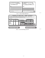
Страница 10: ...10 A11514 Fig 13 Conversion Responsibility Label A11515 Fig 14 Conversion Kit Rating Plate Label ...
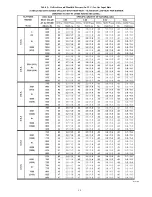
Страница 14: ...14 Table 5 Orifice Size and Manifold Pressure In W C for Gas Input Rate A10184 ...
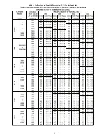
Страница 15: ...15 Table 5 Orifice Size and Manifold Pressure In W C for Gas Input Rate cont A10184A ...
Страница 16: ...16 Table 6 Orifice Size and Manifold Pressure In W C for Gas Input Rate A10185 ...

