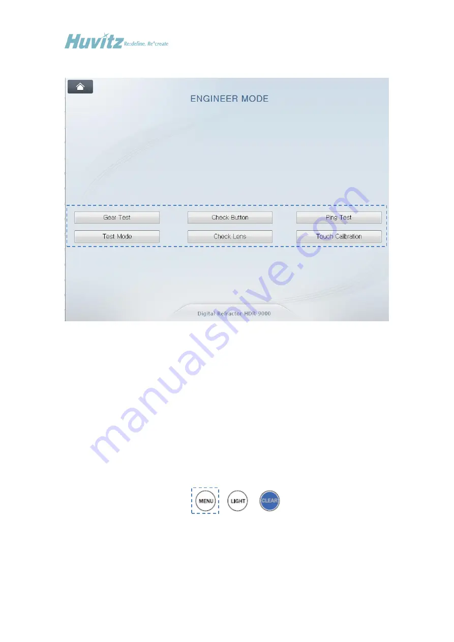
Huvitz HDR-9000 Скачать руководство пользователя страница 55


- 54 - 


[Engineer Mode] 


(2)


Using Check Lens Function 


This  function  is  to  aid  service  engineer  checking  the  status  or  cleaning  lenses  in  the  Refractor 

Body by allowing it inserts lenses one by one and disk by disk. Touching the  “CheckLens” button 

on the display executes the Lens Check function. 


To end using this function and to return to the menu mode, press the MENU button on the keypad 

of Operation Panel or press OK/Cancel button on the display. 


Содержание HDR-9000

Страница 1: ...Service Manual Digital Refractor HDR 9000 HUVITZ Co Ltd...

Страница 2: ...1...

Страница 3: ...n 14 4 1 Removing the Covers 14 4 2 Replacing the Circuit Board 19 4 3 Description of Parts 20 4 3 1 Disk Assembly Patient s Side 20 4 3 2 Disk Assembly Examiner s Side 21 4 3 3 SUB1 GEAR 120 ASS Y 22...

Страница 4: ...3 Appendix 42 A Checking Software Versions 42 B System Setting 44 C Communication 47 D Calibrating Touch Pad 51 E Using Engineer Mode 53 F Upgrading Software 65...

Страница 5: ...ughly before beginning any treatment on the instrument In case the instrument cannot be repaired by the procedures described in this manual contact and inform our technical service department of the d...

Страница 6: ...ng the Technical Support Department at Huvitz HDR 9000 Digital Refractor is consists of three parts Refractor Body Operation Panel and Junction Box The Refractor Body is functionally divided into thre...

Страница 7: ...quired for the engineer who installs and sets up refraction system at customer s place to set up initial system parameters according to customer s needs and environment Parameters listed below are the...

Страница 8: ...d troubleshooting Gear Test It is to aid service engineer checking the status of motors in the Refractor Body Test Mode It is to aid service engineer checking the status of sensors and the movement of...

Страница 9: ...8 Engineer Mode Refer to appendix for more detailed information about this mode...

Страница 10: ...performing the self execution function Once it s turned on and ready perform the self execution mode to see if it operates without problem It s also aimed to give some stress on the mechanical parts o...

Страница 11: ...nce function Press FAR and NEAR button on the display several times Check if the Refractor Body is converging correctly Stop this step when the HDR 9000 Refractor Body is in FAR mode Check the initial...

Страница 12: ...ts group chart button twice Check if the split line of the lens is vertical Change the selection of eye to left by pressing the LEFT button Check if the split line of the lens is vertical The split li...

Страница 13: ...M button with SHIFT pressed on the Operation Panel after the CLM or HLM finishes printing Select and load the data received Check if the data is correct Checking with CCP 3100 Check the System Setting...

Страница 14: ...nu of the Operation Panel for HDC 7000 Set the Chart Connection option to SERIAL or IR Set the Chart Device option to HDC 7000 Store the change by pressing the button OK or HOME button on the display...

Страница 15: ...moving the Covers Unscrew the M3 set screw in the Forehead Adjustment Knob first Remove the Forehead Adjustment Knob Remove the HEADREST Remove the EYE COVER Remove the BOLT CAP with pincette BOLT CAP...

Страница 16: ...15 Unscrew 3 M2 6 screws and remove the CABLE COVER Unscrew 8 M2 6 screws and remove the CASE R CASE L CASE R CABLE COVER CASE L...

Страница 17: ...16 Unscrew M2 6 screws and remove BACK CAP BACK CAP...

Страница 18: ...17 Unscrew 3 M2 6 screws and remove TOP FRONT CASE TOP FRONT CASE...

Страница 19: ...18 Unscrew 6 M2 6 screws and remove INNER CASE L INNER CASE R INNER CASE L INNER CASE R...

Страница 20: ...eplacing the Circuit Board Make it sure to turn off the power before removing the covers or replacing the circuit board Disconnect all the connectors from the circuit board and unscrew 6 screws PCB AS...

Страница 21: ...0 4 3 Description of Parts 4 3 1 Disk Assembly Patient s Side SUB1 GEAR 120 ASSY DISK ASSY MOTOR BOARD CONNECTION GEAR SERIES Cylinder Axis Motor Ass y Cylinder Axis PI Ass y MOTOR BOARD Frame Sub Ass...

Страница 22: ...21 4 3 2 Disk Assembly Examiner s Side SUB1 GEAR 120 ASSY Outer Prism Motor Ass y Inner Prism Motor Ass y Outer Prism PI Ass y Disk_5 Motor Ass y Disk_6 Motor Ass y Disk_4 Motor Ass y...

Страница 23: ...22 4 3 3 SUB1 GEAR 120 ASS Y NO PART NAME 1 M2 5 Screw 2 main_shaft_fixer 3 Teflon_dia24 dia15 T0 1 4 sub1_gear120 5 NTB1024 6 sub_gear_axis...

Страница 24: ...23 4 3 4 SUB1 GEAR 120 DUAL ASS Y NO PART NAME 1 sub_gear_2_shaft 2 sub1_gear120 3 Teflon_dia24 dia15 T0 1 4 main_shaft_fixer 5 NTB1024 6 M2 5 Screw...

Страница 25: ...24 4 3 5 HALL Sensor Ass y NO PART NAME 1 Flat M3 6 Screw 2 PCB ASSY 3 magnet sensor guide Holes for Disk Ass y on right hand Holes for Disk Ass y on left hand...

Страница 26: ...ry with a sharp tool such as a cutter knife Then you can assemble a new sensor at the most close position with the original one Disconnect the connector of the sensor board to be replaced Unscrew and...

Страница 27: ...referring the marks of original position of replaced sensor board fix the new board firmly Connect the connector of the new sensor board Turn on the power and check if the initialization sequence is...

Страница 28: ...Position Open Apertures of 5 disks Open Aperture in a disk which is off centric All Open Apertures are concentric Open Aperture of Disk 6 Incorrect Position Correct Position Open Aperture of Disk 5 Al...

Страница 29: ...28 4 5 Disassembling the Operation Panel Removing procedure for the bottom case of the Operation Panel...

Страница 30: ...29 4 6 Removing the LCD Panel Cover of the Operation Panel...

Страница 31: ...ure below Tilt the LCD monitor 90 degree to open the printer cover Pull the opening lever on the printer cover Pull the remaining paper out Load a new roll of paper into the printer case Check the pri...

Страница 32: ...31 4 8 Disassembling the Junction Box...

Страница 33: ...llow the sequence below 1 Remove the cover glasses from both the patient s and the examiner s side so that a service engineer have access to the internal lenses Before unscrew bolts from the test wind...

Страница 34: ...functions of Engineer Menu mode 4 Execute the Lens Check function in the Engineer Menu mode Refer to appendix for detailed information about operating Lens Check function 5 Insert lenses one by one an...

Страница 35: ...34 5 Trouble shooting 5 1 Wiring Diagram and Board Description 5 1 1 Operation Panel Wiring Diagram...

Страница 36: ...D6EPCB0007 AA PCB ASSY D6 OP SWITCH BOARD ROSWITCH 100 4 1 6400TPH0641 A TPH THERMAL PRINTER HEAD SMP640UG 5 1 7202LGRCLH3 B LCD MONITOR CLAA104XA02CW CPT H3104A HDN3D62 6 1 6440ERO205B A ENCODER REC...

Страница 37: ...36 5 1 2 Refractor Body Wiring Diagram...

Страница 38: ...HEAD RBH 100 2 2 HARNESS ASSY STEP MOTOR PD 3 2 HARNESS ASSY STEP MOTOR TILT 4 2 HARNESS ASSY PI PD 5 2 HARNESS ASSY PI TILT J9 outter prism J10 inner prism J5 CYL1 J7 XC J6 SPECIAL J8 AXIS J1 SPH0 J3...

Страница 39: ...TOR BODY UPPER RIGHT RBM UR 100 18 1 PCB ASSY REFRACTOR BODY LOWER RIGHT RBM LR 100 19 2 PCB ASSY HALL SENSOR BOARD HSB 002 20 2 HARNESS ASSY VD LED 21 2 HARNESS ASSY PI AXIS 22 2 HARNESS ASSY PI INNE...

Страница 40: ...39 5 1 3 Junction Box Wiring Diagram...

Страница 41: ...ITCH KMF1 1163 11 with FUSE SWITCH 2 1 HARNESS ASSY D6 HDR 9000 Inlet to SMPS 3 1 HARNESS ASSY D6 JB Inlet to Earth 4 1 SMPS RPS 60 15 Meanwell 5 1 PCB ASSY D6 JUNCTIONBOX BOARD 6 2 HARNESS ASSY D6 JB...

Страница 42: ...41...

Страница 43: ...unit The Operation Panel includes button communication unit and main GUI unit The Junction Box includes communication unit Each unit is controlled and operated by own operating system software You ca...

Страница 44: ...unit of the Refractor Body RB R Version software version of right hand lens unit of the Refractor Body RB L Version software version of left hand lens unit of the Refractor Body JunctionBox Version s...

Страница 45: ...em to set up some basic and crucial system parameters The system parameter divided two pages and provides 6 parameters to setting up Language Print To Serial Whether to use PC interaction or not Chart...

Страница 46: ...hen touch the Proceed icon on the dialog box The option list is consisted depending on the chart device type selected in the previous step For example if CCP 3100 is selected for chart device option l...

Страница 47: ...Digital Refractor with PC or not PC interface is provided by a special option package named HDRMate Then touch the Proceed icon on the dialog box Setting it to YES would turn on transferring examinat...

Страница 48: ...NECTION It is possible to select to turn on or off the product s wifi function by utilizing the ON OFF at the Connection part If set with DHCP set the two Ap Name SSID and AP Password below and press...

Страница 49: ...name of the wireless router that is used normally The following pop up screen appears when the Find button on the right is pressed on and user can see the list that can be selected presently AP Passwo...

Страница 50: ...eway are the detailed setting that is vitalized when the connection part setting is ON and when set static Virtual keyboard pops up when user touches the box with set value to modify the value When al...

Страница 51: ...figure parameters of each serial ports Actually it is for the direct ports of the junction box According to the configuration of each ports direct1 drect2 and pc it is able to communicate with other d...

Страница 52: ...it is hardly possible to execute the touch calibration function we placed into the function on the Main Menu screen The only press TEST with ALT button to execute the calibration function Guide Mark...

Страница 53: ...s it displays the button five times To complete the calibration You have to click the button five times within 20 seconds Otherwise go back to the previous screen Guide mark Pressing both the five but...

Страница 54: ...neer Menu mode close or exit other menu mode or dialog window and make it in the main examination mode like below Main Examination Mode Pressing buttons on the Operation Panel according to following s...

Страница 55: ...lenses in the Refractor Body by allowing it inserts lenses one by one and disk by disk Touching the CheckLens button on the display executes the Lens Check function To end using this function and to r...

Страница 56: ...55 Dialog box Lens Check In this function mode buttons for serving lens operation are like below Select right or both or left Refractor Body change disk selection Dial changes lens selection...

Страница 57: ...56 Both sides of the Refractor Body Disk Selection Information Lens Selection Number Lens Names...

Страница 58: ...g Test button on the display executes the Ping Test function for communication status check To end using this function and to return to the menu mode press the MENU button on the keypad of Operation P...

Страница 59: ...c noise on any point in between the path between Operation Panel and test target unstable status of power supply certain defect or damage in any circuitry may cause unsuccessful communication So it is...

Страница 60: ...t Mode button on the display executes the Test Mode menu To end using this function and to return to the menu mode press the MENU button on the keypad of Operation Panel or press OK Cancel button on t...

Страница 61: ...pd and convergence The Reference item shows the amount of pulse count input by the operator to the selected target motor The Sensor item shows the read value from the sensor detecting the origin of se...

Страница 62: ...lly the value of sensors for disk position do not exceed 30 and that of sensors for axis pd tilting do not exceed 1000 In the above screen shots one in the left hand shows that the origin of axis moto...

Страница 63: ...eypad in the Operation Panel whether buttons are working properly or not Touching the Check Button button on the display executes the Button Test menu To end using this function and to return to the m...

Страница 64: ...the operator to press button which name is displayed on the dialog box It decides a button is not working properly after giving 3 times of trial when input button is not matching the instructed butto...

Страница 65: ...rs and Gears in the Refractor Body Touching the Gear Test button on the display executes the Button Test menu Dialog box Gear Test 7 Exiting The Menu The HOME button on the display is to exit Engineer...

Страница 66: ...d communication interface Each part of them also has its own software Upgrading targets are like below Refractor Body PD Tilting unit Right hand lens unit Left hand lens unit Refer to the upgrade manu...

Отзывы: