2
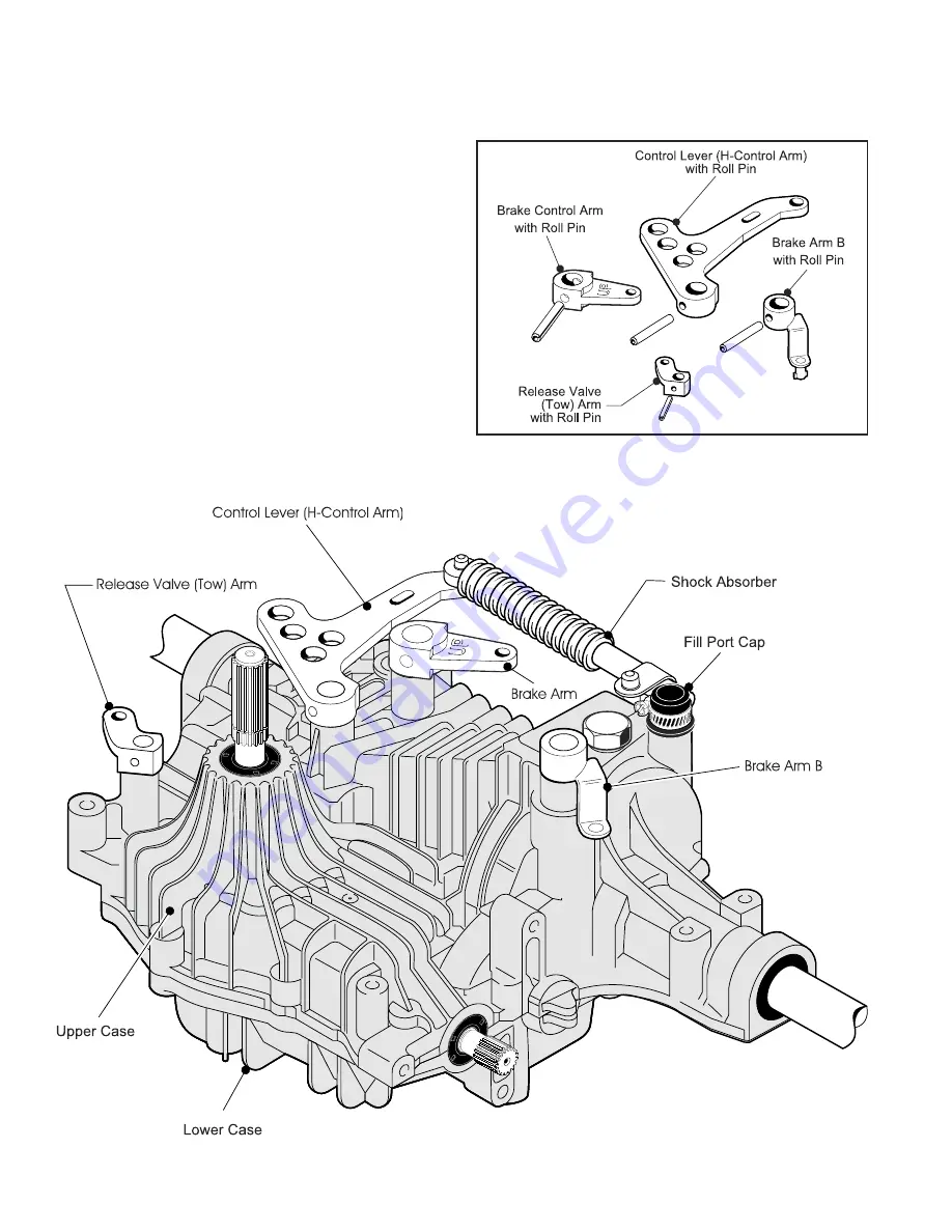
Fig. 3, Levers and Arms Removal
Shock Absorber and Control Arms Removal
(On K61 Models where applicable)
1. Remove the Shock Absorber.
(Fig. 3)
2. Remove the Roll Pin and the H-Control Arm from the
Control Shaft.
(Fig. 4)
3. Remove the Roll Pin and the Brake Arm from the Brake
Shaft.
(Fig. 4)
4. Remove the Roll Pin and Brake Arm “B” from Brake Arm
“A”.
(Fig. 4)
5. Remove the Roll Pin and the (Tow) Release Valve Arm
from the Bypass Shaft.
(Fig. 4)
Fig. 4, Arms and Roll Pins
Содержание Tuff Torq K61
Страница 1: ......
Страница 20: ...17 Tuff Torq K61 Hydrostatic Transaxle Hydraulic Flow Diagram ...


