Husqvarna DM 330 Скачать руководство пользователя страница 21

STATOR – 120 V

Dismantling

Loosen the contact.

Remove both stator screws.

Dismantling

Loosen the flat pin contact from the 
circuit board.

Remove the two screws that hold the 
stator in the motor housing. Nuts on the
opposite side of the stator.

Pull the stator out of the motor housing
by hand. 

Note when reassembling: The flat pin
contact is connected to the circuit board.
Connect the two round cable lugs (d) to
the same carbon brush holder (left side
seen from behind). See page 17.

Pull the stator out of the motor
housing.

Functional test

Fractures to the stator winding are easiest to indicate using the check below.
In general, short-circuited windings can also be identified, particularly if the
short circuit eliminates current in several winding turns. If the short circuit
only eliminates a few turns, the measurement is unlikely to record this. A
fault like this has no noticeable effect on the performance of the motor either.

Resistance measurement – Ohm Ω 

Resistance measurement provides an unequivocal answer as to whether the 
stator winding is fractured. However, the method gives unclear indications for
short-circuited winding turns.

Inductance measurement – Henry (H)

The dimension is “Henry”, abbreviated H (1 H = 1000 mH). Inductance 
measurement is best applied to both identify fractures in the stator winding or
short-circuited winding turns.

Use short measuring cables and lay these close to each other: the easiest way

is to twist them. Cables run in a coiled way give incorrect readings.

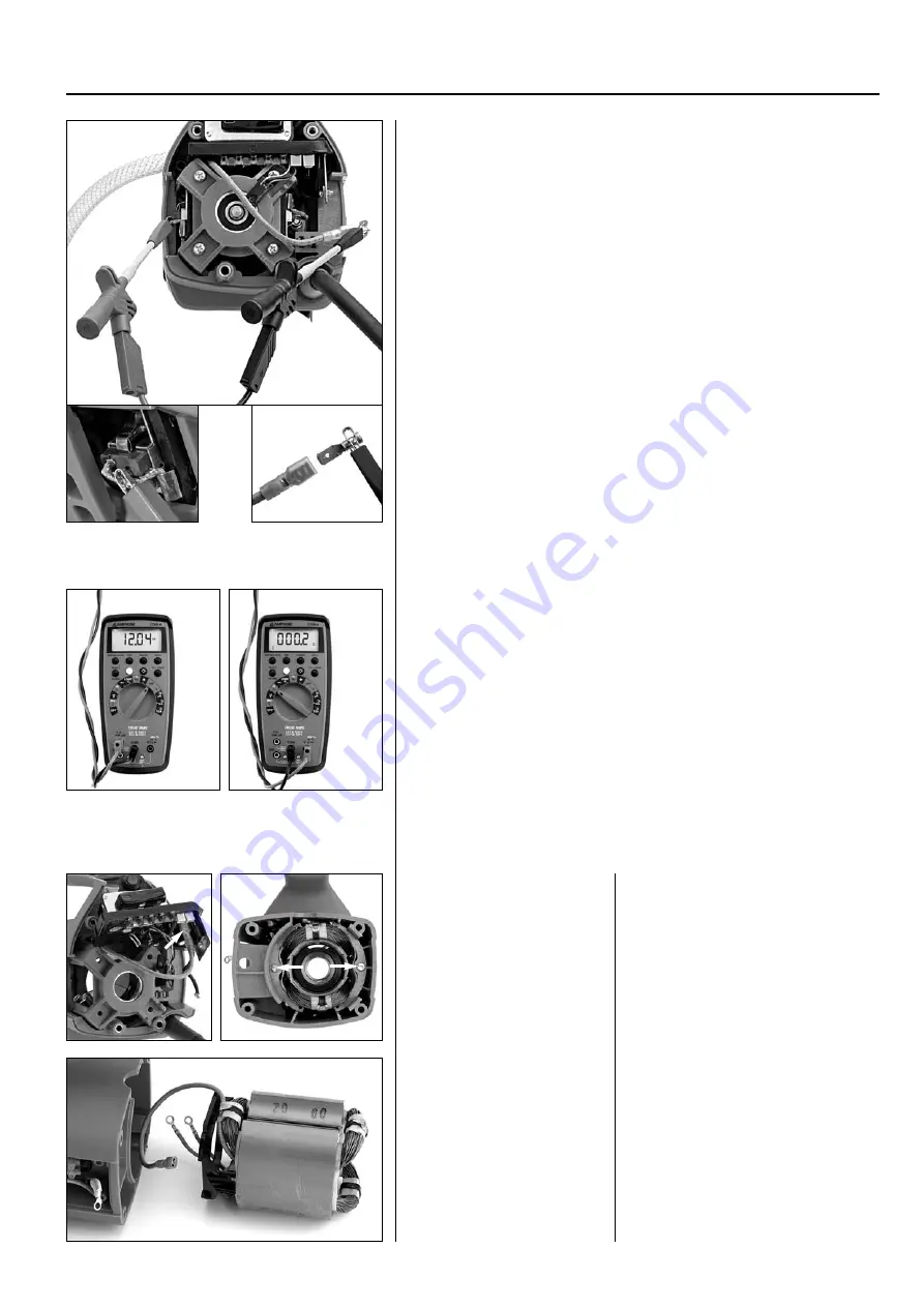
Preparations, illustration 1

Remove the inspection cover to the carbon brushes. 

Left side: Break the electric circuit to the rotor by pulling out the carbon

brush a little and lock with the spring to the side. Connect one of the test
pins to the carbon brush. 

Disconnect the contact to the stator at the circuit board and connect to the

other test pin.

Measured values

Typical measured values for a complete stator are around 10–12 mH. Typical
value for resistance measurement is around 0.2–0.3 ohm.

If the stator winding is fractured you get the value 0 mH. Resistance 

measurement gives a maximum, or immeasurable ohm figure.

Short-circuited winding turns reduce the inductance value. If the value is 

30 % below the typical value, the stator is unfit for use.

A dismantled stator is best tested by measuring both stator windings indivi -
dually. Connect the measurement cables to the flat pin sleeve and one of the
ring cable lugs. Repeat the measurement with the other ring cable lug.

Typical values for a winding (one of two) are for an inductance measure-

ment 4–4.5 mH and for a resistance measurement 0.5–0.6 ohm. Major 
deviations between the windings indicate a defect stator.

mH

Ω

1

15

21

d

Содержание DM 330

Страница 1: ...HUSQVARNA CONSTRUCTION PRODUCTS Workshop manual DM 330 DM 340 ...

Страница 2: ...SLIP CLUTCH 9 7 GEAR HOUSING INTERMEDIATE SHAFT 10 8 GEAR HOUSING SPINDLE SHAFT 12 9 GEAR HOUSING BEARING REPLACEMENT 14 10 CARBON BRUSHES 15 11 WIRING DIAGRAM CABLING 230 V 16 12 WIRING DIAGRAM CABLING 120 V 17 13 ROTOR 18 14 STATOR 230 V 20 15 STATOR 120 V 21 16 TOOLS 22 CONTENTS Page 2 525 59 31 26 HUSQVARNA DM 330 DM 340 ...

Страница 3: ...e drill spindle and is intended for core drill dimensions 25 250 mm The only difference in design is the dimension of the gear wheel on the spindle shaft and the intermediate shaft gear wheel to this DM 340 The gear box is identical to the DM330 Low Speed The motor output is 3600 Watt One external characteristic is the extended motor housing The machine is designed for drill dimensions up to 400 m...

Страница 4: ... two text columns The left hand text column gives a brief explanation and is intended for experienced mechanics whereas the right hand column is a more detailed descrip tion and is intended for mechanics with less experience of repair work for this type of machine Contents The manual is divided into numbered chapters as well as chapter headings that are specified in bold at the top of each page Th...

Страница 5: ... not need to be made on a dismantled machine that is connected to the mains 8 9 10 14 8 SmartStart 9 Circuit breaker 10 Load indicator 11 Mains cable 12 Water connector with valve 13 Attachment 14 Earth fault breaker Work tip The easiest and most convenient way of executing virtually all service work on the DM330 DM340 is with the machine in a vertical position with the drill spindle facing downwa...

Страница 6: ...e radial seals C are defective Water alone indicates that the upper seal is defective while oil indicates that the lower seal to the gear housing is defective A mixture of oil and water shows that both seals are defec tive and that water has leaked into the gear housing Check during service As a rule you should check that the seals are intact on the machines that are to be serviced If the seals sh...

Страница 7: ... tool socket 2 Lift the seal holder to the spindle shaft with a pair of screwdrivers Lubricate the O rings and radial seals when assembling Dismantling assembly 1 Counter stay device facilitates dismantling Lubricate the seal and fit with a suitable sleeve 2 Lift up with screwdrivers Lubricate the O rings and seals when assembling 7 BASIC STRUCTURE 4 504 20 89 01 Oil change in gear housing You can...

Страница 8: ...haft A is removed first followed by the intermediate shaft B although after the upper gear wheel on the spindle shaft C has been removed Note In order to remove the spindle shaft you do not need to remove the primary and intermediate shafts See the Spindle shaft chapter Dismantling primary shaft Remove the oil pipe First lift up the angled nipple Then lift the oil pipe straight up from the control...

Страница 9: ...s the top gear wheel on the primary shaft This gear wheel has a slip clutch to the intermediate shaft to protect the operator and the gear box in the event of jamming Cup springs provide tensioning force between the gear wheel and shaft Flat friction washers are placed on both sides of the gear wheel You can adjust the slip torque if this is necessary by measn of the nut on the shaft Adjust the sl...

Страница 10: ...ear drive Remove the wedge Remove the wedge on the spindle shaft Remove the intermediate shaft Use a standard puller and place the claws under the first gear wheel Create a counterhold by placing a cold chisel for example on the gear housing Press the shaft up using the puller Remove the circlip Remove the circlip using circlip pliers Lift out the gear wheel GEAR HOUSING INTERMEDIATE SHAFT Lift of...

Страница 11: ...r wheel Expand the lock ring using the pliers and lift the ring up Lift off gear wheel Milbar Imperial IR 15R Remove the guide wedge Gear knob Dismantling Drive out the locking pin using a pin punch and remove the knob Remove the lock ring using a small pair of locking ring pliers Milbar Imperial IR 15R or equivalent Press the gear selector into the gear housing Fitting Note the position of the kn...

Страница 12: ...ndle shafts gear wheel is driven by the upper gear wheel of the inter mediate shaft At the upper storage point water is supplied to the drill spindle The transmission in this machine is rarely the cause of any problems Incorrect handling of the machine could however cause the actual spindle shaft to bend or damage the tool bracket The spindle shaft must then be replaced Service work If only the sp...

Страница 13: ...r Fit the outer circlip Fit the circlip into the gear housing Fit the spindle shaft Apply heat around the seat hou sing to around 100 C and cool the shaft if possible Press the shaft into the gear housing Fit the outer circlip Fit the inner circlip Fitting The vice works excellently as a counterhold Tighten the jaws ensuring the bearing s inner ring is supported Knock the bearing into place using ...

Страница 14: ...a suitable socket Removal ball bearing in gear housing There is no level support surface for the counter stay device in the gear housing The adjoining solution with two wooden pieces as a bridge gives the puller a counter hold Alternatively you can use a slide hammer Heating of the gear housing reduces the force needed to remove the bearings Fitting Make the adjoining simple tools to facilitate as...

Страница 15: ...he brush holder to the top level of the brush exceeds 10 mm 1 2 in Worn carbon brushes checking The importance of replacing the brushes in good time is demonstrated by the adjoining illustrations The illustrations to the left show a brush that is worn but still operable Both brushes and the collector have minor scratches in the direction of rota tion which is entirely normal The illustrations to t...

Страница 16: ... connec tions to the circuit board Figure 3 The figure shows how the cables are to be attached in the motor housing Note that the upper bracket has two attachments for the cable The narrow one is designed for machines for 230 V while the thick one is designed for 120 V Figure 4 The figure shows the attachment of the circuit breaker cables black and white Figure 5 The figure shows the connections t...

Страница 17: ...e under the stator cable Figure 3 The figure shows how the cables are attached to the circuit board The stator cable b and the short connection c between the circuit board and carbon brush on the right hand side seen from behind Figure 4 Note how the cables a are to lie in the slot Figure 5 The figure shows the cable routing in the motor housing and the connections to the circuit board View from t...

Страница 18: ...er ring and knock or press out the rotor Functional test Preparations Remove the inspection cover to the carbon brushes Connect a measuring cable to each carbon brush You do not need to be concerned that the stator is connected at the carbon brushes as the stator s circuit board is broken at the circuit board and is therefore not affected by the measurement Measuring cables Use short measuring cab...

Страница 19: ...g replacement Remove the circlip and spring washer under this Knock or press out the gear box cover Cover side bearing replacement Remove the circlip and spring washer under this Knock or press the bearing out of the gear box cover using a suitable socket Fitting the rotor in motor cover Fit using the tool 525 30 02 01 1 Place the gear box cover on the rotor 2 Knock the bearing down until it reach...

Страница 20: ...short measuring cables and lay these close to each other the easiest way is to twist them Cables run in a coiled way give incorrect readings Preparations figure 1 Remove the inspection cover to the carbon brushes The stator winding is divided at the circuit board and is connected in the following way Pull out the contacts to the stator at the circuit board Connect the contacts using a cable fitted...

Страница 21: ...rement is best applied to both identify fractures in the stator winding or short circuited winding turns Use short measuring cables and lay these close to each other the easiest way is to twist them Cables run in a coiled way give incorrect readings Preparations illustration 1 Remove the inspection cover to the carbon brushes Left side Break the electric circuit to the rotor by pulling out the car...

Страница 22: ...rna Lock ring pliers Make Milbar Imperial IR 15R Plier for small external lock rings without pickup holes Dismantling and fitting of the intermediate shaft s lock ring Dismantling and fitting of the gear knob Multimeter Make Amprobe 37XR A One of few universal instru ments that can also measure inductance H Henry Check of electric motor s functions Counter stay device There are a number of manu fa...

Страница 23: ...www husqvarnacp com 525 59 31 26 English 2009 02 ARNE PALMQUIST ...

Отзывы: