142
MODIFICA POSIZIONE ED
ALTEZZA MANUBRIO
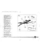
La posizione (a) e l'altezza (b)
del manubrio possono
essere modificati per meglio
adattarsi alle Vostre esigenze di
guida. Per effettuare le
operazioni, rimuovere il
cavallotto superiore (1) e quello
inferiore (2) previo smontaggio
delle relative viti di fissaggio (3)
e (4).
a) Modifica posizione manubrio
Ruotare di 180° il cavallotto
inferiore per ottenere
l’avanzamento o l’arretramento
(10mm- 0.04 in.) della
posizione del manubrio rispetto
a quella iniziale.
b) Modifica altezza manubrio
Rimuovere il distanziale
inferiore (A) e sostituire la vite
(4) con una di lunghezza L=65
mm..
Ultimata l’operazione, serrare le
viti (3) a 2,75-3,05 kgm (27-30
Nm; 19.9-22 Lb/ft) e le viti (4) a
2,0-2,2 kgm (19,6-21,6 Nm;
14.5-15.9 Lb/ft).
HANDLEBAR POSITION AND
HEIGHT CHANGE
The handlebar position (a) and
height (b) can be changed for
better suiting Your driving
requirements. To effect these
operations, remove the upper
screw (3), upper clamp (1),
lower screw (4) then lower
clamp (2).
a) Handlebar position change
Turn the lower clamp (2) 180° to
move forward or backward
(10mm- 0.04in.) the handlebar
position with respect to the
original setup.
b) Handlebar height change
Remove the lower spacer (A)
then replace the screw (4) with
a new one of L=65 mm (2.56
in.) height.
Once these operations are
completed, tighten the screws
(3) to 2,75-3,05 kgm (27-30
Nm; 19.9-22 Lb/fts) and the
screws (4) to 2,0-2,2 kgm (19,6-
21,6 Nm; 14.5-15.9 Lb/fts).
MODIFICATION DE LA
POSITION ET DE L'HAUTEUR
DU GUIDON
La position et l'hauteur du
guidon ils peuvent être changée
pour mieux s'adapter à Vos
exigences de guide. Pour
effectuer cette opération, il est
nécessaire de démonter les vis
(3), le etau supérieur (1), les vis
(4) et le etau inférieur (2).
a) Modification de la position du
guidon
Tourner le etau inférieur (2) de
180° pour avancer ou reculer
(10mm - 0.04in.) la position du
guidon en relation à cette
initiale.
b) Modification de l'hauteur du
guidon
Enlever l'entertoise inférieur (A)
et remplacer la vis (4) avec une
de longueur L=65 mm
Exécuter le remontage en
opérant inversement et en
serrant les vis (3) aux 2,75-3,05
kgm (27-30 Nm; 19.9-22 Lb/ft)
et les vis (4) aux 2,0-2,2 kgm
(19,6-21,6 Nm; 14.5-15.9 Lb/ft).
LENKER POSITION UND
HÖHE HÄNDERN
Die Position und die Höhe des
Lenkers kann geändert erden,
um sich besser Eur
Erfordernissen von Führung
des Motorrades anzupassen.
Um diese Operation
vorzunehmen, ist er notwendig
die Schrauben (3) die höhere
Klemme (1) die Schrauben (4)
und die untere Klemme (2)
auszusteigen.
a) Lenker position händern
Verlaufen dann zu im Kreise
von 180° die untere Klemme (2)
schwingen um übrigzulassen
oder zurückziehen (10mm -
0.04in.) die Position des
Lenkers in Beziehung zu jener
Initiale.
b) Lenker höhe händern
Entfernen das unteren
Distanzstück (A) und ersetzen
die Schraube (4) mit einem von
Länge L=65 mm
Die Remontage zu 2,75-3,05
kgm die Schrauben (3)
verschließend, ausführen (27-
30 Nm; 19.9-22 Lb/ft) und die
Schrauben (4) zu 2,0-2,2 kgm
(19,6-21,6 Nm; 14.5-15.9 Lb/ft).
7-250-450-510-2005-OK 28-06-2005 15:26 Pagina 142
Содержание 2006 SMR 400
Страница 102: ...90 5 250 450 510 2005 OK 28 06 2005 15 16 Pagina 98 ...
Страница 103: ...91 5 250 450 510 2005 OK 28 06 2005 15 16 Pagina 99 ...
Страница 106: ...94 5 250 450 510 2005 OK 28 06 2005 15 16 Pagina 102 ...
Страница 107: ...95 5 250 450 510 2005 OK 28 06 2005 15 16 Pagina 103 ...
Страница 249: ...229 11a 250 450 510 2005 OK 23 06 2005 13 50 Pagina 229 ...
Страница 251: ...231 11a 250 450 510 2005 OK 23 06 2005 13 50 Pagina 231 ...
Страница 266: ...246 TE SMR TE SMR TE SMR TE SMR 11c 250 450 510 2005 OK 23 06 2005 13 53 Pagina 246 ...
Страница 267: ...247 TE SMR 11c 250 450 510 2005 OK 23 06 2005 13 53 Pagina 247 ...
Страница 271: ...251 11c 250 450 510 2005 OK 23 06 2005 13 53 Pagina 251 ...
Страница 320: ...300 MEMORANDUM 13 indice OK 23 06 2005 13 58 Pagina 300 ...


