background image


Humidex 

20 


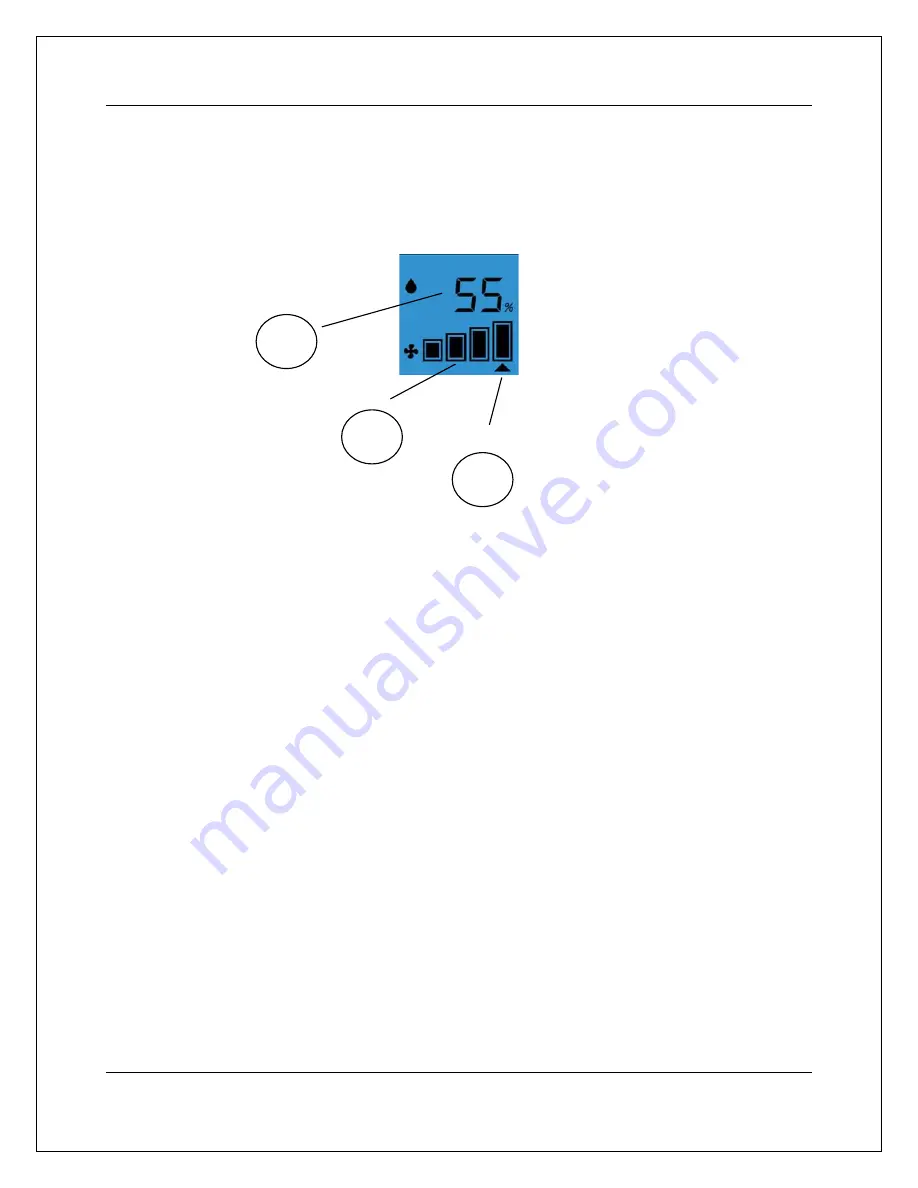
The LCD Display 


The LCD Display consists of: 

1-


User Set Humidity Level 

2-


Operating Fan Speed 

3-


Desired Max Fan Speed Indicator  


Navigating the LCD Menu 

The HCS has an LCD display that allows the unit to display information about its operation.  The 

LCD display also has a 4 button user interface that allows the user to navigate the LCD menu and 

change settings such as the maximum operating speed of the unit, the dehumidistat setting, as well as 

access the unit’s built in override mode.  The following sections explain how to navigate the LCD 

menu and change the settings, as well as how to access the override mode.  

1


3


Содержание HCS-BS-HDEX

Страница 1: ...7 Humidex HCS Rev 1 5En Installation Owner s Manual English This Manual Covers the Following Models HCS BS HDEX HCS CS HDEX Manufactured by ClairiTech Innovations Inc 1095 Ohio Rd Boudreau Ouest NB Canada E4P 6N4 ...

Страница 2: ... NOT MAKE MORE THAN ONE TURN WITH THE DUCT AND THE DUCTWORK SHOULD NOT BE LONGER THAN 3 FEET IN TOTAL UNLESS RIGID DUCTING IS USED SEE 7 COMBUSTION APPLIANCE PRESENT IN DWELLING 7 IDEAL LOCATION OF THE UNIT 7 REPLENISHMENT AIR TO BASEMENT FROM UPSTAIRS 9 DUCTING 9 Installation 10 FACTORS TO CONSIDER 10 SELECTING THE DUCT LOCATION 10 PREPARING THE HUMIDEX FOR INSTALLATION 11 PUTTING THE UNIT TOGETH...

Страница 3: ...7 What is the dew point 18 NEW INSTALLATIONS IN THE SUMMER 18 LCD Display and Control Layout 19 THE LCD DISPLAY 20 NAVIGATING THE LCD MENU 20 ENTERING THE MAIN MENU 21 RELATIVE HUMIDITY MENU 21 OVERRIDE TIMER MENU 22 CHANGING FAN SPEEDS 22 NOTES ON LCD DISPLAY FEATURES 23 Most Common Issues 24 MOLD MILDEW AND MUSTY SMELL 24 Specifications 25 TECHNICAL DATA 25 DIMENSIONS 25 ...

Страница 4: ...nd serial number located on the side of the unit Product Name Model Date of Manufacturing Date of Purchase Serial Dealer Name If Any Please Note the above information before contacting us For the Following Inquiries Service Parts Accessories Additional Customer Information Please contact us by Phone 1 888 533 1348 Email support humidex ca Website www humidex ca ...

Страница 5: ...rranty you must fill out and return the warranty card as soon as possible If your unit is not registered a proof of purchase will be necessary should it require any services You can also register your warranty online http www clairitech com warranty ...

Страница 6: ...s beyond the time period described herein on behalf of ClairiTech Innovations Inc The warranties described herein shall be the sole and exclusive warranties granted by ClairiTech and shall be the sole and exclusive remedy available to the purchaser Correction of defects in the manner and for the period of time described herein shall constitute complete fulfillment of all liabilities and responsibi...

Страница 7: ...cal or hole saw 6 Drill with a concrete bit Phillips or Robinson Screw Driver Measuring Tape Hammer Pencil For concrete cinderblock or brick installation use a hammer drill with chiseling ability x 16 long and a chisel bit 1 thick Key Installation Facts 1 Unit must be installed at floor level approximately 3 off the floor 2 Replenishment air has to flow from upstairs into the basement or crawlspac...

Страница 8: ...re below the humidity setting on the Humidex as they usually are during the heating season the Humidex operates at approx 25 of the capacity of a standard bathroom fan or by introducing make up air inside the building A fresh air kit Air Supply Ventilator is available from your Humidex dealer to help relieve the effects of negative air pressure in the building Ideal location of the Unit Air drawn ...

Страница 9: ...Humidex 8 The area within a radius of 4 feet around the unit should be clear to allow the air to be pulled into the vents ...

Страница 10: ...air from outside Generally for improved performance it is best to keep all exterior basement crawlspace doors windows and vents closed at all times Please check to make sure there are no openings leaks around windows doors vents or other places where outside humid air can enter the basement crawlspace Make sure that A C Ducts are properly sealed and that all A C Leads to the basement are closed Su...

Страница 11: ... dampest coldest level of your dwelling Try to find an outside wall to accommodate a 6 hole to the exterior of the house where no electrical wires or pipes are present The unit should be installed with a minimum distance of 8 feet from any source of heat Make sure that you do not install the unit in a boiler room It is important to maximize the distance between the unit and the source of replenish...

Страница 12: ...nd the pilot hole Now using a hole saw with the pilot hole as a guide drill a 6 hole Brick or Concrete Wall There are two ways of going through brick or concrete The first method consists of using a hammer drill Make holes approximately 5 8 with the hammer drill 1 apart through the brick in a circular shape outlining the 6 hole Finish cutting the outer edge of the hole using a chisel If a hammer d...

Страница 13: ...ing metal fastening screws A cover plate can be used to close the gap between both halves if necessary Using aluminum tape or duct tape seal the seam in the back where the two halves join together Note When installing the optional 24 extension remove top cap and straighten the 90 elbow Use the 6 galvanized pipe to extend the length needed Cut the pipe to the proper length before snapping it togeth...

Страница 14: ...f the flex pipe inside the hole in the wall a few Small 9 16 Screw can be used to affix the flex to the mount Leaving a 1 inch gap between the top of the unit and the ceiling drill pilot holes through the lips of the unit and the wall Apply the four plastics anchors on the wall with the help of a hammer Secure the HCS BS or HCS CS Unit to the wall using the four 1 inch screws provided ...

Страница 15: ... may cause a wind noise inside the house If this is the case an anti gust hood AGH 990 is available from your Humidex dealer Wiring and Attaching the Control Once the exhaust unit has been mounted the control needs to be installed and connected It is crucial that the control is placed in the proper location The HCS control must be installed on the main floor and as close to the source of the reple...

Страница 16: ...o the wall with the screws provided With the control mounted on the wall the wires must then be stripped and connected following this guide Yellow Wire B Green Wire A Black Wire GND Red Wire VCC Once the wires have been connected the control can be closed and the screw tightened This connection must then be repeated in order to link the main exhaust unit Wire the green connector following the same...

Страница 17: ... insert it into the main exhaust unit Now that the control has been installed and connected to the main exhaust unit the HCS can be plugged into any 115V outlet Note A grounded extension cord with a maximum length of 10 feet may be used if necessary ...

Страница 18: ...r operation mode Note For the unit to function properly and to allow the unit to provide the best energy efficient ventilation and humidity control all windows doors with access to the outdoor and vents to the outdoor should be closed to prevent an excessive amount of outdoor air from entering directly into the house Vacant Homes Performance results are maximized when the building is occupied If h...

Страница 19: ...hat might produce unhealthy living conditions in your home odors molds etc New Installations in the Summer The late spring and early mid summertime temperature in most basements remains at approximately 59 to 66 F 15 to 19 C whereas the air entering the basement from the upstairs of the house will generally be in the range of 75 to 85 F 24 to 29 C with a relative humidity of 70 to 75 This air will...

Страница 20: ... Control Layout The following sections of this operating manual refer to the user interface presented below The user interface consists of 1 LCD Display 2 Up Arrow Button 3 Down Arrow Button 4 Cancel Button 5 Ok Button 1 2 3 4 5 ...

Страница 21: ...display information about its operation The LCD display also has a 4 button user interface that allows the user to navigate the LCD menu and change settings such as the maximum operating speed of the unit the dehumidistat setting as well as access the unit s built in override mode The following sections explain how to navigate the LCD menu and change the settings as well as how to access the overr...

Страница 22: ... to the main screen press the cancel button Relative Humidity Menu Once the relative humidity menu has been selected the screen will change in order to allow the user to change the desired humidity level Using the arrows keys will allow you to increase or decrease the desired RH value in increments of 5 To accept a new value select OK Button or the Cancel button to return to the main menu If the w...

Страница 23: ...Arrow Buttons to cycle through the different override timer options and once the desired override time is chosen press the Ok Button to begin the override or the Cancel button to return to the main menu If the wrong time is entered repeat this procedure Changing Fan Speeds To change the maximum fan speeds simply select the fan speed menu from the main menu Once the display has changed to the Fan s...

Страница 24: ...fan speed unless the override mode is running The control will choose the proper fan speed depending on humidity temperature and dew point conditions Notes on LCD display features 1 The LCD display on this unit has a built in backlight to allow for better readability in darker locations This backlight turns on when any button on the control panel is pressed and turns off after no button has been p...

Страница 25: ...om the upstairs to the downstairs Increase ventilation in remote areas with a portable fan Any exposed pipes and ducts should be insulated Cinder block basement walls should be sealed with plastic vapor barrier or sealant Dirt floor in crawl space or basement should be covered with vapor barrier Sump pump should be equipped with a cover Rainwater from the roof should be directed away from the base...

Страница 26: ...ity Sq Ft HCS BS HDEX 0 30 34 230 2 400 HCS CS HDEX 0 30 34 230 3 000 All Units require a 115 VAC electrical outlet Dimensions Model Height In Width In Depth In HCS BS HDEX 85 96 11 5 8 5 HCS CS HDEX 32 11 5 8 5 A 24 Inch extension section is available if extra height is required ...

Отзывы:

Похожие инструкции для HCS-BS-HDEX