


Incremental Hollow Shaft Encoder FGH 40
12
FGH40_MANUAL-en_R10(2018-10-31)ID74492.doc
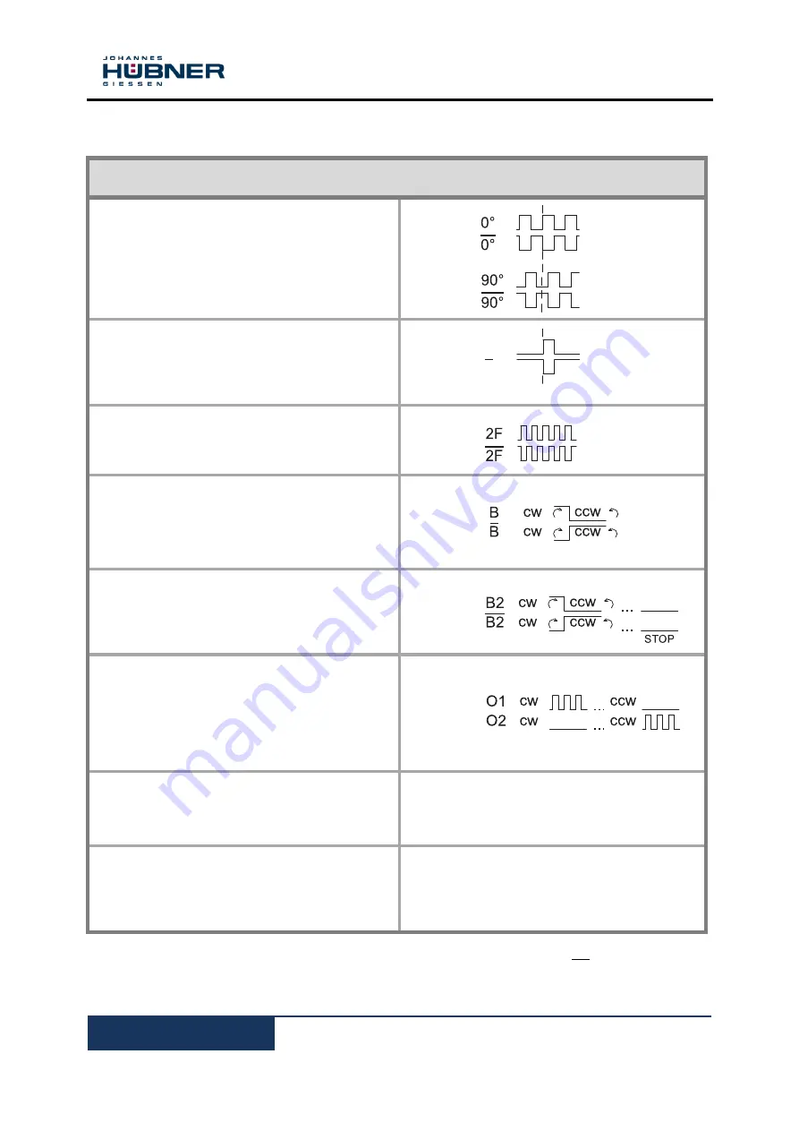
Signal outputs for pulse rates (square wave pulses)
Basic version
Basic channel 0° (A) and pulse channel 90° (B)
Internal system diagnostics with error
output (ERROR)
Each with inverted signals
Option N
Reference pulse (N) mechanically defined; one
square-wave pulse per revolution; with inverted
signal
Option 2F
Twice as many pulses as basic channel by
combining the 0° and 90°channels
Option B
Rapid direction of rotation detection at each edge
of the 0° and 90°channels
Can be combined with Option F
Option B2
Rapid direction of rotation detection at each edge
of the 0° and 90° channels; additional standstill
recognition
Option B3
Rotation-dependent output signals. This option
supports counter cards with separate UP/DOWN
pulse inputs. Basic channel signals are issued at
option output 1 when rotation is clockwise and at
option output 2 when rotation is counterclockwise.
Option S
Electronic overspeed switch with two
independently programmable switching points
See separate Operating and Assembly
Instructions EGS
®
40
Fiber optic option
As an alternative to conventional signal
transmissions via copper cables encoder signals
can also be transmitted via fiberoptic cables.
Max. frequency 100 kHz
The signal sequence 0°, 90° applies for clockwise rotation seen from the drive shaft direction.
To obtain the same signal sequence for counter clockwise rotation the clamp 0°, 90° has to be
connected see connection diagram.
N
N


