background image

5

e

Installing Cables

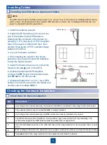
1. Install the antenna support.

2. Install the GPS antenna and connect one 
end of the feeder to the GPS antenna. 
Waterproof the connector of the feeder by 
adopting 1+3+3 (one layer of PVC insulation 
tape, three layers of waterproof tape, then 
another three layers of PVC insulation tape) 
waterproof method.

3. Lay out the feeder outdoors.

4. When leading the feeder to the house, 
prepare a drip loop and screw the fasteners 
to seal the feeder window.

5. Install the feeder indoors and connect the 
feeder to the 

surge

port on the SPD. 

6. (Optional) Install the GPS amplifier. 
Connect the 

RF in 

port to the antenna side 

and 

RF out 

to the device side.

7. (Optional) Install the 1-to-2 or 1-to-4 GPS 
divider. Connect its one end to the feeder and 
another end to multiple eBBUs. 

Installing the GPS Antenna System and Cables

f

Checking the Hardware Installation

a

NO.

Check Item

1

According to the network planning, the boards in the BBU are inserted in the proper slots and secured.

2

The subrack which is used to install the BBU is steady installed. 

3

According to the network planning, the BBU cables are properly installed and secured.

4

The GPS antenna must be installed in an area with an open view and far from high buildings. The 
vertical view angle of the GPS antenna must be greater than or equal to 90

°

.

5

The horizontal distance between the GPS antenna and the surge protector must be greater than or equal 
to 2 m.

6

When leading the feeder to the equipment room, prepare a drip loop outdoors and seal the feeder window.

7

The 

protect

end of the surge protector for the equipment must face the cabinet.

Check Items for Device Installation

a

GPS antenna

Feeder

Feeder window

GPS amplifier

GPS SPD

1-to-2 divider

The GPS antenna can be installed under a tower or on a tower. Here is the process of installing a GPS antenna 
under a tower. For details about how to install a GPS antenna on a tower, 

see “Installing a GPS Antenna on a 

tower” in 

eNodeB Product Documentation.

NOTE

Содержание V100R005C10

Страница 1: ...lectrostatic damage to the subrack Only when the BBU install in TP48200A and APM30H cabinets subrack cable claws are configured Other cabinets carry on next step directly NOTE The figure shows only installation slots for the main processing board core network processing board baseband processing board fan module and power module in the typical configuration If you need to install the USCUb22 UEIU ...

Страница 2: ...inet interior using cable ties 2 Install a ground cable for the GPS SPD 3 Install a clock signal cable for the GPS SPD 1 Connect the N50 straight female connector of the clock signal cable to the PROTECT terminal on the GPS SPD using a torque wrench to a torque of 4 N m 2 Connect the SMA male connector of the GPS clock signal cable to the GPS port on the UMPT LMPT USCUb22 4 Connect the GPS SPD jum...

Страница 3: ...ler of an optical module and insert the optical module into the SFP0 SFP1 port on the LMPT the FE GE1 port on the UMPTb2 or the XGE1 XGE3 port on the UMPTe3 Then raise the puller 2 Remove the dustproof cap from the optical fiber Connect an FE GE optical fiber to the optical module 4 Install the winding pipe at the end of the optical fiber Ensure that the winding pipe is installed at the position b...

Страница 4: ...BBU cable claw positions 5 Install the winding pipe at the end of the optical fiber Ensure that the winding pipe is installed at the position between the optical fiber connector and the first optical fiber binding point The method is the same as that for installing an optical fiber Installing a GPS Clock Signal Cable 1 Connect the SMA end of the GPS clock signal cable to the GPS port on the UMPT L...

Страница 5: ...g to the network planning the boards in the BBU are inserted in the proper slots and secured 2 The subrack which is used to install the BBU is steady installed 3 According to the network planning the BBU cables are properly installed and secured 4 The GPS antenna must be installed in an area with an open view and far from high buildings The vertical view angle of the GPS antenna must be greater th...

Страница 6: ... power system The screws are tightened In addition the inputs or outputs are not short circuited 3 The redundant part of the power cable or PGND cable is cut rather than coiled 4 The terminals at two ends of each power cable or PGND cable are securely soldered or crimped 5 The bare wires and the terminal handles at the wiring terminals are coated with heat shrink tubing 6 A flat washer and a sprin...

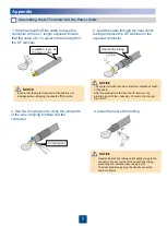
Страница 7: ...of the bare crimping terminal and the conductor 4 Install the heat shrink tubing Crimping tool NOTICE Heat the heat shrink tubing until it tightly clings to the connector Do not overheat the heat shrink tubing preventing the insulation layer being burnt The heat shrink tubing must be fixed to cover the cable conductor NOTICE Ensure that the metal conductor of the cable is not damaged when strippin...

Отзывы: