4
Installing Cables
Connecting Ethernet Cables or Optical Fibers to the Main Processing Board
c
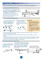
1. Connect the RJ45 connector at one end of
the Ethernet cable to the
FE/GE0
port on the
UMPT/LMPT, the
FE/GE1
port on the LMPT, or
the
FE/GE2
port on the UMPTe3.
2. Connect the other end of the FE/GE
Ethernet cable to the electrical port of an
external transmission device.
c2 Installing an FE/GE Ethernet Cable
b
Connecting a CPRI Optical Fiber
d
1. Unbuckle the optical module
and then insert the optical
module into the
CPRI
port on
the UBBP/LBBPd4 board.
2. Remove the dust-proof
cap from the optical
connector, and insert the
optical fiber into the optical
module.
3. Route the optical fiber along the left side of the cabinet and lead the cable out through the
bottom cable outlet of the cabinet.
4. Bind the cables properly using the optical fiber binding strap based on BBU cable claw
positions.
5. Install the winding pipe at the end of the optical fiber. Ensure that the winding pipe is installed
at the position between the optical fiber connector and the first optical fiber binding point. (The
method is the same as that for installing an optical fiber.)
Installing a GPS Clock Signal Cable
1. Connect the SMA end of
the GPS clock signal cable to
the
GPS
port on the
UMPT/LMPT board.
2. Lay out the GPS clock signal cable
in the cabinet, and lead the end with a
type N female connector through the
cable outlet module to the
Protect
port on the GPS surge protective
device (SPD).
UMPTb2
UMPTb2
Layout of the GPS clock
signal cable in the cabinet
e
NOTICE
•
When the optical fiber remote
distance between BBU and eRRU is
from 10 km to 20 km, a 3 dB optical
attenuator needs to be added
between the optical module of
UBBP/LBBPd4 board and CRPI
optical fiber.
•
If you use an optical fiber with an LC
connector on each end, connect
TX
port on the BBU board to the
RX
port
on the eRRU, and connect the
RX
port on the BBU board to the
TX
port
on the eRRU.

