2
Installing a GPS SPD
Installing Cables
Installing PGND Cables
a
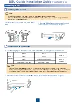
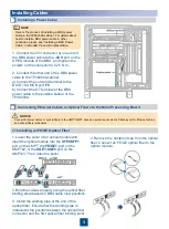
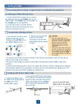
1. Connect the M4 OT terminal at one end of the BBU PGND cable to
the OT terminal on the BBU.
2. Connect the M6 OT terminal at the other end to an external ground
bar or ground screw.
Some cables in this section need to be prepared manually. For details about how to prepare the cables, see
Appendix.
NOTE
This installation
applies only to
cabinets provided by
customers.
NOTE
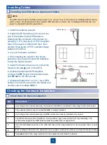
1. Bind the GPS SPD to the left side panel of
the cabinet interior using cable ties.
2. Install a ground cable for the GPS SPD.
3. Install a clock signal cable for the GPS SPD:
(1)Connect the N50 straight female connector of the
clock signal cable to the
PROTECT
terminal on the
GPS SPD using a torque wrench to a torque of 4 N·m.
(2)Connect the
SMA
male connector of the GPS
clock signal cable to the
GPS
port on the
UMPT/LMPT/USCUb22.
4. Connect the GPS SPD jumper to the
SURGE
terminal on the GPS SPD using a torque wrench to a
torque of 4 N·m.
Here is the process of binding a GPS SPD in the TP48200A cabinet. For details about how to install a GPS SPD
in other scenarios, please
see “(Optional) Installing a GPS SPD” in
eNodeB Product Documentation.
NOTE

