background image

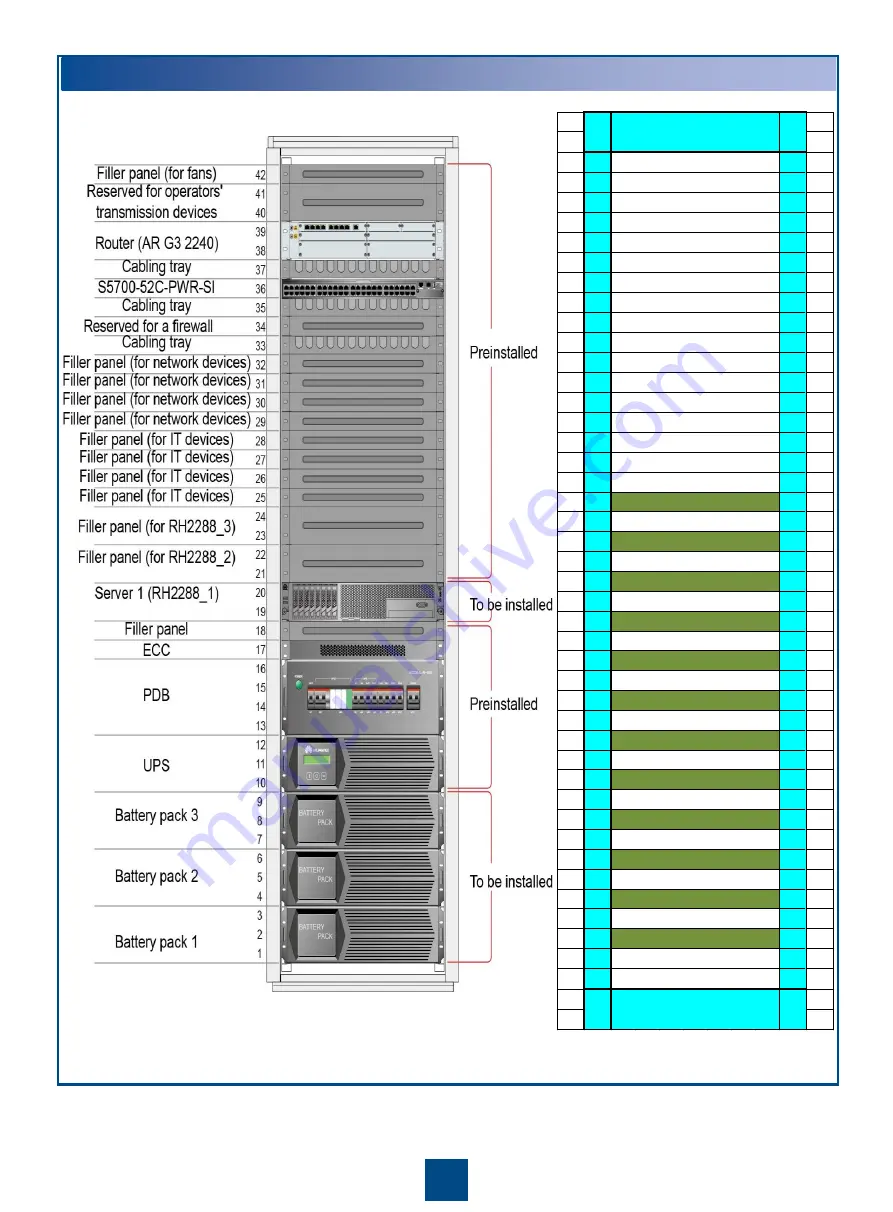
Installation Planning 

For 600 terminals 

All-in-One cabinet 

42 1U

1U 42

41 1U

1U 41

40 1U

1U 40

39 1U

1U 39

38 1U

1U 38

37 1U

1U 37

36 1U

1U 36

35 1U

1U 35

34 1U

1U 34

33 1U

1U 33

32 1U

1U 32

31 1U

1U 31

30 1U

1U 30

29 1U

1U 29

28 1U

1U 28

27 1U

1U 27

26 1U

1U 26

25 1U

1U 25

24 1U

1U 24

23 1U

1U 23

22 1U

1U 22

21 1U

1U 21

20 1U

1U 20

19 1U

1U 19

18 1U

1U 18

17 1U

1U 17

16 1U

1U 16

15 1U

1U 15

14 1U

1U 14

13 1U

1U 13

12 1U

1U 12

11 1U

1U 11

10 1U

1U 10

9

1U

1U

9

8

1U

1U

8

7

1U

1U

7

6

1U

1U

6

5

1U

1U

5

4

1U

1U

4

3

1U

1U

3

2

1U

1U

2

1

1U

1U

1

Network distribution
cabinet (front view)

S3752 switch

S3752 switch

S3752 switch

S3752 switch

S3752 switch

S3752 switch

S3752 switch

S3752 switch

S3752 switch

S3752 switch

S3752 switch

S3752 switch

Network distribution
cabinet (front view)

Содержание V100R001C00

Страница 1: ...ypical configuration suite and extension components The installation of extension components varies with the number of terminals to be supported while the installation of the typical configuration suite remains unchanged The Micro DC applies to scenarios in which 150 300 and 600 terminals are supported If customers require more than 1 hour backup power install a battery cabinet Cabinet installatio...

Страница 2: ...itoring system including 1 ECC 1 temperature and humidity sensor 1 water leakage sensor 2 door status sensors and 1 smoke sensor Basic Storage Computing RH2288 1 Battery pack 3 Monitoring suite outside the cabinet including the sensor mounting arm smoke sensor and IP camera 1 AP6010DN 3 Network distribution cabinet 1 S3752 office edition 8 Micro DC All in One cabinet 1 1 AR2240 1 S5752 1 PDB 1 UPS...

Страница 3: ...3 Installation Planning For 150 terminals All in One cabinet ...

Страница 4: ... 25 1U 1U 25 24 1U 1U 24 23 1U 1U 23 22 1U 1U 22 21 1U 1U 21 20 1U 1U 20 19 1U 1U 19 18 1U 1U 18 17 1U 1U 17 16 1U 1U 16 15 1U 1U 15 14 1U 1U 14 13 1U 1U 13 12 1U 1U 12 11 1U 1U 11 10 1U 1U 10 9 1U 1U 9 8 1U 1U 8 7 1U 1U 7 6 1U 1U 6 5 1U 1U 5 4 1U 1U 4 3 1U 1U 3 2 1U 1U 2 1 1U 1U 1 Network distribution cabinet front view S3752 switch S3752 switch S3752 switch S3752 switch S3752 switch S3752 switch...

Страница 5: ...3 1U 1U 23 22 1U 1U 22 21 1U 1U 21 20 1U 1U 20 19 1U 1U 19 18 1U 1U 18 17 1U 1U 17 16 1U 1U 16 15 1U 1U 15 14 1U 1U 14 13 1U 1U 13 12 1U 1U 12 11 1U 1U 11 10 1U 1U 10 9 1U 1U 9 8 1U 1U 8 7 1U 1U 7 6 1U 1U 6 5 1U 1U 5 4 1U 1U 4 3 1U 1U 3 2 1U 1U 2 1 1U 1U 1 Network distribution cabinet front view S3752 switch S3752 switch S3752 switch S3752 switch S3752 switch S3752 switch S3752 switch S3752 switch...

Страница 6: ...one power distribution unit PDU is preinstalled in the All in One cabinet and numbered PDU1 More PDUs are numbered in an ascending order from outside to inside and from left to right The rack is divided into 42 U 1 U 1 75 in numbering from 1 to 42 from the bottom up For the network device occupying more than 1 U the label records the smallest height number For example if a 2 U network device occup...

Страница 7: ...from the cabinet Install the ground cable Prepare the power cable connectors Connect power cables 3 Combine and level cabinets There is one reinforcing bracket at the height of 22 U 38 5 in in the front and rear of the cabinet Before removing the front reinforcing bracket remove the filler panels at the height of 23 U to 25 U 40 25 in to 43 75 in Mains inlet port Power cable Ground cable ...

Страница 8: ...C Lead the cable from the GPRS antenna into the cabinet through the cable hole on the top of the cabinet Route the cable along the external side of the mounting bar on the right of the rear of the cabinet to the ECC at the cabinet bottom Then bind the cable to the cable tray under the ECC Checking Quantities and Types of Goods Inspecting Goods Installing the Typical Configuration Suite Installing ...

Страница 9: ...customers require more than 1 hour backup power install a battery cabinet or battery packs Before connecting battery packs using power cables loosen screws beside the protection cover for the wiring terminals and remove the protection cover Install the protection cover after connecting battery packs using power cables Positions for installing Battery Packs ...

Страница 10: ...es space for another two servers Customers can install two more servers if one RH2288 cannot meet requirements If three RH2288 servers are installed number them RH2288_1 RH2288_2 and RH2288_3 Install the servers in the right place No ground cable is required because the RH2288 is configured with AC power modules Server installation Network cable connection for a server Network cable connection for...

Страница 11: ...s for the sensor mounting arm base Rotate tube 1 to adjust the sensor mounting arm until it is in the highest installation position Then adjust the IP camera based on the object to be monitored Checking Quantities and Types of Goods Inspecting Goods Installing the Typical Configuration Suite Installing Extension Components Installing the Integrated Sensor Mounting Arm for All Scenarios ...

Страница 12: ...into the correct position on the transfer board Insert the connector of the IP camera signal cable into the correct position on the ECC Checking Quantities and Types of Goods Inspecting Goods Installing the Typical Configuration Suite Installing Extension Components Optional Installing the WLAN AP for All Scenarios For details about how to install the wireless local area network WLAN access point ...

Страница 13: ...and IT cabinet connect to the PDU input ports on the power distribution box PDB in the All in One cabinet In this way power can be supplied to the network distribution cabinet and IT cabinet Checking Quantities and Types of Goods Inspecting Goods Installing the Typical Configuration Suite Installing Extension Components Optional Installing the Battery Cabinet for All Scenarios If customers require...

Страница 14: ...es Tighten the bolts that are not properly secured 3 Check that battery cables are correctly connected to battery terminals 4 Check that screws at the ground point are secured Tighten the screws that are not properly secured 5 Check that the voltage between the mains input neutral wire and the ground cable is less than 5 V AC Commissioning mechanical performance 1 Switch on and off all circuit bre...

Страница 15: ...lling the Typical Configuration Suite Installing Extension Components Inspecting Devices Before Power on Performing Power On and Power Off Tests PDU input circuit breaker Input circuit breaker on the UPS backplane UPS front panel Circuit breaker on the battery pack ...

Страница 16: ... about 1s The UPS is started 2 Change the working mode for the UPS For example to change from the parallel mode to the single mode perform the following steps a In the main window hold down the MENU button for 5s Alarm Silence OK is displayed b Release the MENU button for 0 6s and then hold it down for 0 6s Alarm Silence OK is displayed c Hold down for 1s The parallel mode changes to the single mo...

Отзывы: