10
4
Verifying the Installation
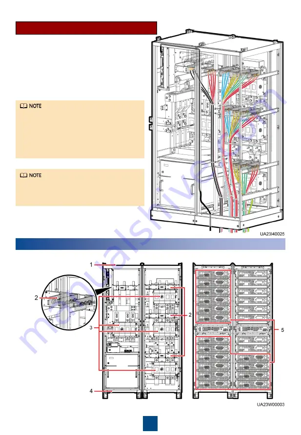
Scenario 2: Routing Cables from the Bottom
For the screw specifications and torque
used for connecting cables in a bottom
cable routing scenario, refer to the top
cable routing scenario. This section only
shows the cable routes in the bottom cable
routing scenario.
For the cable connection method for the
TN-C system, see the user manual.
1. Remove the cable covers from the bottom of
the cabinet, drill holes in the covers, attach
grommet strips to the hole edges for
protecting cables, and reinstall the cable
covers.
2. Connect power cables and signal cables.
1. Check that there is no foreign matter in the cabinet.
(1) Top of the cabinet
(2) Wiring terminal
blocks
(3) Switches
(4) Bottom of the cabinet
(5) Rear of the modules


