U9200 Maintenance Manual
INTERNAL
(2012-06-13)
Huawei Proprietary and Confidential
Copyright © Huawei Technologies Co., Ltd.
Page 39 of 80
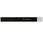
8.18 Installing and Screwing the Rear Cover
Step 1 Use tweezers to tear off the
camera protective film.
Step 2 Take the rear cover, and
open the volume key.
Step 3 Align one side of the rear
cover with the main board, and then
install it to the correct position.
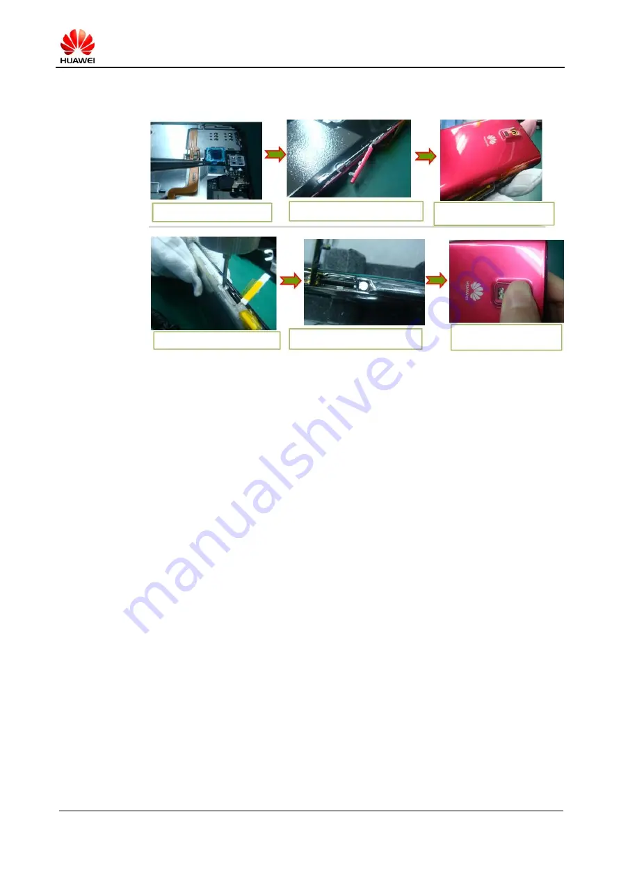
Step 4 Run the electric screwdriver to
screw the rear cover with square head
screws.
Step 5 Paste anti-dismantle labels to
the screws.
Step 6 Tear off the liner from the
rear camera. Paste lens on it, and
press it for three seconds.