13
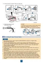
Knocking Off the Barrier Chip from a Cable Hole
4.2
• Before connecting the PE cable, AC input power
cable, and AC output power cable for the first
time, knock off the barrier chips from the cable
holes 1 and 2 for the AC input power cable and
the cable hole for the AC output power cable.
• The edges of the cable holes for the AC input
and output power cables are sharp. You are
advised to use a file to smooth the edge of the
cable hole. Protect yourself from being hurt
during the operation.
• The FEK-65B waterproof connectors of Mirai
Industry Co., Ltd. are recommended for the cable
holes for the AC input and output power cables.
No. Cable
Recommended Model or Specifications
Cross-sectional Area
Range of the Cable
1
AC input power cable
Three-core outdoor copper cable (operating
temperature ≥ 90°C) with M5 OT terminals
3.5
–8 mm
2
2
AC output power
cable
Three-core outdoor copper cable (operating
temperature ≥ 90°C) with M12 OT terminals
150
–200 mm
2
3
Single-phase input
power cable
Three-core outdoor copper cable (operating
temperature ≥ 90°C) with an M4 OT terminal (PE)
2
–5.5 mm
2
4
RS485
communications
cable
Two-core outdoor shielded RS485
communications cable (single-core rigid cable
recommended)
0.25
–1 mm
2
5
PE cable
Single-core green outdoor copper cable with an
M6 OT terminal
3.5
–22 mm
2
13
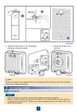
Routing a Cable Through a Waterproof Connector (COM)
4.3
1. Remove the locking cap and
plug from the waterproof
connector.
2. Route the cable through the
locking cap and then the
waterproof connector.
3. Connect the cable.
4. Tighten the locking cap.
5
Connecting Cables
Preparing Cables
5.1
Prepare cables and OT terminals based on site requirements.
Содержание SmartACBox
Страница 23: ...22 ...

