background image

PowerCube 5000 
User Manual (SmartLi 100Ah) 

9 Parts Replacement 


Issue 02 (2020-03-17) 

Copyright © Huawei Technologies Co., Ltd. 

135 


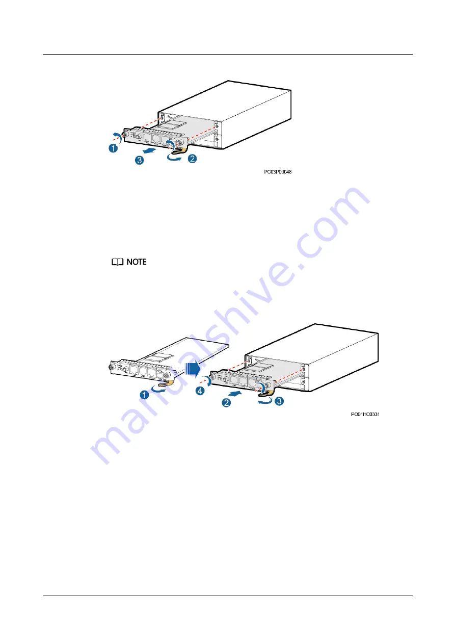
Figure 9-13


Removing an NIM01C3 


Step 5


Remove the SIM card from the SIM card slot of the NIM01C3, and insert it into the SIM card 
slot of the new NIM01C3. Skip this step if no SIM card is installed. 

Step 6


Place the new NIM01C3 at the entry to the appropriate slot in the monitoring unit subrack, 
and push the NIM01C3 until its front panel is flush with the front panel of the monitoring unit 
subrack. 


The NIM01C3 must be installed in the original position (upper slot). Otherwise, it cannot work properly. 

Step 7


Push the handle inwards until it is engaged, and then tighten the screws. 

Figure 9-14


Installing an NIM01C3 


Step 8


Connect the signal cables to the original positions on the NIM01C3 panel. 

Step 9


Disconnect the ground cable for the ESD wrist strap, and remove the ESD wrist strap and 
ESD gloves. 

----End 

Follow-up Procedure 

Pack the removed component and have it sent to the local Huawei warehouse. 

Содержание PowerCube 5000

Страница 1: ...PowerCube 5000 User Manual SmartLi 100Ah Issue 02 Date 2020 03 17 HUAWEI TECHNOLOGIES CO LTD ...

Страница 2: ...tomer All or part of the products services and features described in this document may not be within the purchase scope or the usage scope Unless otherwise specified in the contract all statements information and recommendations in this document are provided AS IS without warranties guarantees or representations of any kind either express or implied The information in this document is subject to c...

Страница 3: ...ioning engineers Data configuration engineers Maintenance engineers Symbol Conventions The symbols that may be found in this guide are defined as follows Symbol Description Indicates a hazard with a high level of risk which if not avoided will result in death or serious injury Indicates a hazard with a medium level of risk which if not avoided could result in death or serious injury Indicates a ha...

Страница 4: ...not related to personal injury equipment damage and environment deterioration Change History Changes between document issues are cumulative The latest document issue contains all changes made in previous issues Issue 02 2020 03 17 Updated the monitoring description Updated the description about certain cable connections Added the description about emergency power off EPO Issue 01 2019 10 30 This i...

Страница 5: ...dule HSU 18 2 3 2 Bypass Module BPS 19 2 3 3 Monitoring Unit 21 2 3 3 1 SMU02S 22 2 3 3 2 UIM02C 25 2 3 3 3 NIM01C3 29 2 3 3 4 GIM01C 32 2 3 3 5 Energy Monitoring Module ECU01A 33 2 3 3 6 Monitoring Interface Module MUS01C 35 2 3 3 7 Monitoring Display Unit MDU 38 2 4 Smart Lithium Battery Cabinet SmartLi 39 2 4 1 Model Description 41 2 4 2 Energy Storage Module ESM 41 2 4 3 System Battery Control...

Страница 6: ...t Power Cable 75 3 7 2 Installing an AC Input Power Cable 76 3 7 3 Installing Signal Cables Between Lithium Battery Cabinets 78 3 7 4 Installing Cables Between the Lithium Battery Cabinet and the ICC Cabinet 80 3 7 5 Installing Cables Between the ICC Cabinet and the Isolation Transformer 82 3 7 6 Installing an AC Output Cable for the Isolation Transformer 83 3 7 7 Installing Control Cables Between...

Страница 7: ... 118 8 1 3 ECM01A Troubleshooting 119 8 1 4 MUS01C Troubleshooting 120 8 1 5 HSU Troubleshooting 121 8 1 6 BPS Troubleshooting 122 8 1 7 Circuit Breaker Troubleshooting 123 8 1 8 Clearing the EPO State 123 8 2 Lithium Battery Cabinet Troubleshooting 123 9 Parts Replacement 125 9 1 Parts Replacement for the ICC Cabinet 125 9 1 1 Replacing an AC SPD 125 9 1 2 Replacing a Circuit Breaker 128 9 1 3 Re...

Страница 8: ...ii 9 2 3 Replacing an SBCU 142 10 FAQ 144 10 1 How Do I Install an Expansion Sleeve 144 10 2 Preparing Cable Terminals 145 10 3 Installing a Dry Contact Signal Cable 146 11 Technical Specifications 148 A Alarm List 151 B Alarm List for the Lithium Battery Cabinet 161 C EMC 165 D Acronyms and Abbreviations 167 ...

Страница 9: ...or maintaining the equipment The safety instructions in this document are only supplements to local laws and regulations Huawei will not be liable for any consequences of the following circumstances Operation beyond the conditions specified in this document Installation or use in environments which are not specified in relevant international or national standards Unauthorized modifications to the ...

Страница 10: ...urface or terminal measure the contact point voltage and ensure that there is no risk of electric shock After installing the equipment remove idle packing materials such as cartons foam plastics and cable ties from the equipment area In the case of a fire immediately leave the building or the equipment area and turn on the fire alarm bell or make an emergency call Do not enter the building on fire...

Страница 11: ...es cannot be exposed to an outdoor environment for a long period of time Before operations ensure that the equipment is firmly secured to the floor or other solid objects such as a wall or an installation rack Do not use water to clean electrical components inside or outside of a cabinet Do not change the structure or installation sequence of equipment without permission Do not touch a running fan...

Страница 12: ...f the sources and degree of various potential hazards in equipment installation operation maintenance Trained personnel personnel who are technically trained have required experience are aware of possible hazards on themselves in certain operations and are able to take protective measures to minimize the hazards on themselves and other people Operators operation personnel who may come in contact w...

Страница 13: ...e that a distance of at least 30 mm exists between the cables and heat generating components or areas This prevents damage to the insulation layer of the cables Do not route cables behind the air intake and exhaust vents of the equipment Ensure that cables meet the VW 1 flame spread rating requirements Bind cables of the same type together When routing cables of different types ensure that they ar...

Страница 14: ...rements To prevent fire due to high temperature ensure that the ventilation vents or heat dissipation system are not blocked when the equipment is running Install the equipment in an area far away from liquids Do not install it under areas prone to condensation such as under water pipes and air exhaust vents or areas prone to water leakage such as air conditioner vents ventilation vents or feeder ...

Страница 15: ...evant personnel Carry the operation machinery and tools properly to prevent them from falling off and causing injuries Personnel involving working at heights are not allowed to throw objects from the height to the ground or vice versa Objects should be transported by tough slings hanging baskets highline trolleys or cranes Ensure that guard rails and warning signs are set at the edges and openings...

Страница 16: ... and confirm its load bearing capacity Do not overload it Ensure that the ladder is securely positioned The recommended angle for a ladder against the floor is 75 degrees as shown in the following figure An angle rule can be used to measure the angle Ensure that the wider end of the ladder is at the bottom or protective measures have been taken at the bottom to prevent the ladder from sliding When...

Страница 17: ...ble or heavy objects on the cabinet Be cautious to avoid injury when moving heavy objects When moving the equipment by hand wear protective gloves to prevent injuries Move or lift the equipment by holding its handles or lower edges Do not hold the handles of modules such as power supply units fans and boards that are installed in the equipment because they cannot support the weight of the equipmen...

Страница 18: ...diately with clean water and go to the hospital for medical treatment Use dedicated insulated tools Move batteries in the required direction Do not place a battery upside down or tilt it Keep the battery loop disconnected during installation and maintenance Use batteries of specified models Using batteries of other models may damage the batteries Dispose of waste batteries in accordance with local...

Страница 19: ...ed lead acid batteries To prevent fire or corrosion ensure that flammable gas such as hydrogen is properly exhausted for lead acid batteries Lead acid batteries emit flammable gas when used Ensure that batteries are kept in a well ventilated area and take preventive measures against fire Battery Leakage Battery overheating causes deformation damage and electrolyte spillage When the electrolyte ove...

Страница 20: ... manufacturer When handling a lithium battery do not place it upside down tilt it or bump it with other objects Keep the lithium battery loop disconnected during installation and maintenance Do not charge a battery when the ambient temperature is below the lower limit of the operating temperature charging is forbidden at 0 C Low temperature charging may cause crystallization which will result in a...

Страница 21: ...tem developed for areas where grid power is unavailable It features efficient energy yield reliable power supply and intelligent operation and maintenance O M As a comprehensive and systematic solution this system uses modular design and provides intelligent monitoring It supports solar input three phase four wire AC output and online capacity expansion of power modules Figure 2 1 Networking ...

Страница 22: ... 2 Electrical conceptual diagram 2 2 Working Mode PV Inverter The PV input is supplied with DC voltage through the MPPT and then the inverter converts the DC voltage into AC voltage output In this case the bidirectional DC DC unit works to provide charging energy for the battery Figure 2 3 Working mode of the PV inverter ...

Страница 23: ... the DC voltage to the AC voltage output In this case the bidirectional DC DC works to provide charging energy for the internal busbar of the HSU Figure 2 4 Working mode of the batteries DG DG input supplies power to loads through the bypass module Figure 2 5 DG working mode 1 The DG input supplies power to loads through the bypass module and charges the battery through the reverse PFC and bidirec...

Страница 24: ...PowerCube 5000 User Manual SmartLi 100Ah 2 Products Issue 02 2020 03 17 Copyright Huawei Technologies Co Ltd 16 Figure 2 6 DG working mode 2 ...

Страница 25: ...2 7 Interior 1 Power module HSU 2 Bypass module BPS 3 Monitoring unit 4 Solar input switches 5 Battery cold start button 6 AC input switch 7 Auxiliary AC output switch 8 AC input SPD and SPD circuit breaker 9 AC input port 10 Positive terminal block for batteries 11 Positive PV input port 12 Ground bar 13 EPO button 14 Monitor screen 15 AC output switch ...

Страница 26: ...nit The HSU implements DC DC conversion for PV input to charge batteries or stabilizes the bus voltage and then converts it into sine wave output through the inverter DC AC It also provides the power factor correction PFC function When there is no power from PV modules and batteries the DG supplies power to the PFC unit and battery bidirectional conversion unit to charge the batteries The HSU also...

Страница 27: ...in g Frequency 0 5 Hz on for 1s and off for 1s There is a PFC soft start failure alarm DC bus pre charging has failed On Protection is triggered by external conditions or temporary malfunction is caused by internal factors Fault indicator Red Off There is no internal fault or EPO On Protection protective lockout EPO or module unreadiness is caused by internal component faults Table 2 2 Specificati...

Страница 28: ...scription Power indicator Green Steady on The system is working in bypass mode Blinking slowly The bypass has no output blinking at 0 2 Hz on for 2 5s and off for 2 5s Blinking fast The bypass is not configured or the DSP software is being upgraded blinking at 4 Hz on for 0 125s and off for 0 125s Off The bypass CPLD software is being upgraded Alarm indicator Yellow Steady on A minor alarm is gene...

Страница 29: ...600 mm Weight 50 kg Operating temperature 25 C to 55 C Rated output capacity 200 kVA Rated input and output voltage 380 V AC 400 V AC 415 V AC 2 3 3 Monitoring Unit Figure 2 10 Overview 1 Energy control module ECM 2 Space for the communications expansion module NIM01C3 3 Space for the DG interface module GIM01C 4 Monitoring module SMU02S 5 User interface module UIM02C 6 Monitoring interface module...

Страница 30: ...able 2 5 Indicator description Name Color Status Description Running indicator Green Off The SMU is faulty or has no DC input Blinking slowly 0 5 Hz The SMU is running properly and communicating with the host properly Blinking fast 4 Hz The SMU is running properly but fails to communicate with the host properly Minor alarm indicator Yellow Off No minor or warning alarm is generated Steady on A min...

Страница 31: ...o log in again if no button is pressed within 1 minute To increase or decrease a parameter value quickly hold down or To restart the SMU hold down and for 10 seconds To increase or decrease the LCD contrast ratio hold down and or for 2 seconds SD Card Slot The SD card has a maximum of 32 GB memory USB Port You can insert a USB flash drive into the USB port to upgrade software set up a site rapidly...

Страница 32: ...d rate 125 kbit s CAN protocol NOTE All these ports are protected by a security mechanism Figure 2 12 Communication port pins Table 2 8 FE port pin definitions Pin Signal Description 1 TX Transmits data over FE 2 TX 3 RX Receives data over FE 6 RX 4 5 7 and 8 N A Table 2 9 RS485 RS232 port pin definitions Pin Signal Description 1 TX Transmits data over RS485 2 TX 4 RX Receives data over RS485 5 RX...

Страница 33: ...ts to the ground 8 N A Table 2 10 CAN port pin definitions Pin Signal Description 1 RX Receives data over RS485 2 RX 3 N A 4 TX Transmits data over RS485 5 TX 6 N A 7 CANH CAN high level signal 8 CANL CAN low level signal 2 3 3 2 UIM02C Panel Figure 2 13 Panel 1 Communications port 2 Dry contact output ports 3 Dry contact input ports 4 Sensor ports ...

Страница 34: ...mperature sensor Dry contact input ports DIN1 Dry contact input 1 DIN2 Dry contact input 2 DIN3 Dry contact input 3 DIN4 Dry contact input 4 DIN5 Dry contact input 5 DIN6 Dry contact input 6 Dry contact output ports ALM1 Dry contact output 1 ALM2 Dry contact output 2 ALM3 Dry contact output 3 ALM4 Dry contact output 4 ALM5 Dry contact output 5 ALM6 Dry contact output 6 ALM7 Dry contact output 7 AL...

Страница 35: ... s 4800 bit s 9600 bit s 14400 bit s 19200 bit s 115200 bit s Master slave Modbus and YDN1363 protocols Connects to a downstream device such as the intelligent battery detector NOTE The COM port is protected by a security mechanism Figure 2 14 Pins in the COM port Table 2 13 COM port pin definitions Pin Signal Remarks 1 RX Receives data over RS485 2 RX 4 TX Transmits data over RS485 5 TX 6 PGND Pr...

Страница 36: ...chnologies Co Ltd 28 Sensor Ports Figure 2 15 Pins in sensor ports Table 2 14 UIM02C pin definitions Silk Screen No Pins TEM HUM 1 12 V 2 ENV_TEMP 3 12 V 4 ENV_HUM WATER 1 12 V 2 WATER 3 GND 4 TEMP1 1 GND 2 TEMP1 TEMP2 1 GND 2 TEMP2 GATE 1 GATE 2 GATE SMOKE 1 SMOKE 2 12 V BTEMP 1 GND 2 BTEMP ...

Страница 37: ... 15 Indicator description Indicator Color Status Description 4G indicator Green Steady on The dial up connection is in the data service state Blinking at a period of 2s on for 0 1s and then off for 1 9s The network has been registered Blinking at a period of 2s on for 0 1s off for 0 1s on for 0 1s and then off for 1 7s A network is in search or no network is connected Alarm indicator Red Off No al...

Страница 38: ... 1200 bit s 2400 bit s 4800 bit s 9600 bit s 14400 bit s 19200 bit s 115200 bit s Supports master slave protocols and Modbus protocols Supplies 12 V power COM2 port Baud rate 1200 bit s 2400 bit s 4800 bit s 9600 bit s 14400 bit s 19200 bit s 115200 bit s Supports master slave protocols and Modbus protocols Supplies 12 V power COM3 CAN port Baud rate 1200 bit s 2400 bit s 4800 bit s 9600 bit s 144...

Страница 39: ...S485 data 3 12 V Supply power 4 RS485 RS485 data 5 RS485 RS485 data 6 NA 7 NA 8 GND Grounded Table 2 18 Description for the COM3 CAN port pins Pin Signal Description 1 RX Receives data over RS485 2 RX 3 NA 4 TX Transmits data over RS485 5 TX 6 GND Grounded 7 CANH CAN high level signal 8 CANL CAN low level signal Table 2 19 Description for the COM4 port pins Silk Screen Signal Description R RS485 R...

Страница 40: ...ts 9 CAN communications port 10 Alarm indicator Indicators Table 2 20 Indicator description Name Color Status Remarks RUN indicator Green Off The module is faulty or has no DC input Blinking slowly 0 5 Hz The module is running and communicating with the host properly Blinking fast 4 Hz The module is running properly but does not communicate with the host properly ALM indicator Red Reserve Ports Ta...

Страница 41: ...mally open port RST2 M Common port NO DO normally open port Fuel level detection port AI1 12 V power supply Detect the fuel level Analog signal AI2 12 V power supply Analog signal Communicati ons port COM R RS485 data Used for RS485 communication R RS485 data CAN CAN data Used for CAN communication CAN data 2 3 3 5 Energy Monitoring Module ECU01A Panel The energy monitoring module ECM panel silk s...

Страница 42: ...teady on The module is active and working properly Blinking slowly 0 5 Hz The module is standby and ready to work Blinking fast 4 Hz The module software is being loaded Alarm indicator Yellow Off No minor or warning alarm is generated Steady on A minor or warning alarm is generated Fault indicator Red Off No critical or major alarm is generated Steady on A critical or major alarm is generated Port...

Страница 43: ...ion port 5 48 V power port 6 CAN_OUT port 7 COM_OUT port Ports Table 2 24 Port description Port Type Silk Screen Description Dry contact input for battery circuit breaker status detection BF1 Dry contact input 1 BF2 Dry contact input 2 BF3 Dry contact input 3 BF4 Dry contact input 4 BF5 Dry contact input 5 BF6 Dry contact input 6 EPO detection port NO When NO and 12 V close EPO is triggered 12V NC...

Страница 44: ...ns Ports Table 2 25 Port description Communications Port Communications Parameter Communications Protocol CAN_IN Baud rate 250 kbit s CAN protocol CAN_OUT Baud rate 250 kbit s CAN protocol COM_IN CAN baud rate 250 kbit s Modbus baud rate 9600 bit s CAN and Modbus protocols COM_OUT Baud rate 9600 bit s Modbus protocol Figure 2 21 Pins in a communications port Table 2 26 CAN_IN port pin definitions ...

Страница 45: ...us low level 3 12V Power supply 8 GND Ground 4 7 Reserved Table 2 28 COM_IN port pin definitions Pin Signal Description 1 RS485 RS485 data 2 RS485 RS485 data 7 CANH CAN bus high level 8 CANL CAN bus low level 3 6 Reserved Table 2 29 COM_OUT port pin definitions Pin Signal Description 1 RS485 RS485 data 2 RS485 RS485 data 3 12V Power supply 4 RS485 RS485 data 5 RS485 RS485 data 6 Reserved 7 Reserve...

Страница 46: ...cator 2 LCD touchscreen Table 2 30 Indicator description Name Status Color Meaning Status alarm indicator Steady on Red The ICC cabinet has generated a critical alarm Yellow The ICC cabinet has generated a major or minor alarm Green The ICC cabinet is running properly or has generated a warning Off N A The MDU is faulty or the communications cable with 12 V power supply is not connected ...

Страница 47: ...h for the MDU 7 SD Reserved 8 DIP switch Reserved Functions The MDU allows you to operate cabinets view the running status and alarms and set parameters Specifications and Features Dimensions 175 mm H x 264 mm W x 40 mm D 2 4 Smart Lithium Battery Cabinet SmartLi The lithium battery cabinet consists of multiple energy storage modules ESMs a battery control unit BCU and a system battery control uni...

Страница 48: ...can be used together You do not need to manually charge or discharge the replacement ESMs to adjust the capacity Figure 2 24 Product structure 1 Alarm indicator 2 Running indicator 3 EPO button 4 SBCU 5 ESMs 6 BCU 7 Battery breaker QF1 8 BCU power switch QS1 9 Battery cold start breaker QF2 Table 2 32 Indicator description Name Color Status Meaning RUN Green On Communication is normal Off Batterie...

Страница 49: ...ries 672 V when 14 ESMs are configured 3 Capacity 100AH 100 Ah battery capacity 4 Configuration type F with a display with an EPO button master cabinet S without a display without an EPO button slave cabinet 2 4 2 Energy Storage Module ESM The ESM is an energy storage unit composed of lithium ion batteries It features better charge and discharge performance longer service life and less self discha...

Страница 50: ... ESM positive terminal 6 ESM negative terminal 7 Terminal cover Table 2 34 Indicator description Name Color Status Meaning RUN AL M Red On The ESM is faulty Off The BMU is upgrading Green On The SmartLi is being discharged Blinking at 0 2 Hz The SmartLi is faulty or in standby mode Blinking at 0 5 Hz The SmartLi is being charged Blinking at 4 Hz Failed to locate the physical location Off The BMU i...

Страница 51: ...arance Figure 2 27 SBCU 1 Status indicator 2 LCD touchscreen Table 2 35 Indicator status Name Status Color Description Status alarm indicator On Red The SmartLi has generated a critical alarm and the buzzer buzzes Yellow The SmartLi has generated a minor alarm Green The SmartLi is running properly or has generated a warning Off N A The SBCU is powered off ...

Страница 52: ...ve to import and export the configuration file export run logs and upgrade software 8 SD Reserved 9 DIP switch Reserved Functions The SBCU allows you to operate cabinets view the running status and alarms and set parameters Specifications and Features Dimensions 175 mm H x 264 mm W x 40 mm D 2 4 4 Battery Control Unit BCU The BCU generates alarms for cells and ESMs in the lithium battery cabinet p...

Страница 53: ...rts TEMP1 Monitors the ambient temperature inside the cabinet TEMP2 Monitors the ambient temperature outside the cabinet GATE Door status sensor port SMOKE Smoke sensor port WATER Water sensor port Dry contact ports EPO1 Dry contact of the EPO button connected to the EPO button connected to the EPO2 port on the other module hand in hand EPO2 Dry contact for the EPO button connected to the EPO1 por...

Страница 54: ...unications port Table 2 38 Pin definitions for the BCU IN and BCU OUT ports Pin Signal Description 1 RS485 RS485 data positive 2 RS485 RS485 data negative 3 12V Supplies power 4 RS485 RS485 data positive 5 RS485 RS485 data negative 6 GND Grounding 7 CANH CAN bus high level 8 CANL CAN bus low level Table 2 39 Indicator description Silk Screen Name Colo r Status Description RUN Running indicator Gre...

Страница 55: ...t Frequency 2 Hz The communication is interrupted ALARM Fault indicator Red Steady on A fault or critical alarm is generated Off No fault or critical alarm is generated CHG Charge indicator Green Steady on In charge mode Off In open circuited state or discharge mode DCHG Discharge indicator Green Steady on In discharge mode Off In open circuited state or charge mode ...

Страница 56: ... Technologies Co Ltd 48 2 5 Isolation Transformer 2 5 1 Isolation Transformer ITC80D Figure 2 31 Appearance 1 AC SPD 2 Alarm cable port 3 Output disconnector 4 Ground bar 5 N input bar 6 SPD fuses 7 N output bar 8 AC input L bar Table 2 40 Specifications Item Specifications Capacity 80 kVA ...

Страница 57: ...tions Application scenario 2 modules 60 kW Voltage 380 V 400 V 415 V Dimensions H x W x D 2000 mm x 800 mm x 850 mm Installation mode Floor mounted 2 5 2 Isolation Transformer ITC120D Figure 2 32 Appearance 1 AC SPD 2 Alarm cable port 3 Output disconnector 4 Ground bar 5 N input bar 6 SPD fuses 7 N output bar 8 AC input L bar ...

Страница 58: ... 02 2020 03 17 Copyright Huawei Technologies Co Ltd 50 Table 2 41 Specifications Item Specifications Capacity 120 kVA Application scenario 3 modules 90 kW Voltage 380 V 400 V 415 V Dimensions H x W x D 2000 mm x 800 mm x 850 mm Installation mode Floor mounted ...

Страница 59: ... 51 2 5 3 Isolation Transformer ITC200D Figure 2 33 Appearance 1 AC SPD 2 Alarm cable port 3 Output disconnector 4 Ground bar 5 N input bar 6 SPD fuses 7 N output bar 8 AC input L bar Table 2 42 Specifications Item Specifications Capacity 200 kVA Application scenario 5 modules 150 kW Voltage 380 V 400 V 415 V ...

Страница 60: ...ologies Co Ltd 52 Item Specifications Dimensions H x W x D 2000 mm x 800 mm x 850 mm Installation mode Floor mounted 2 5 4 Isolation Transformer ITC400D Figure 2 34 Appearance 1 AC SPD 2 Output disconnector 3 Alarm cable port 4 Ground bar 5 N input bar 6 SPD fuses 7 N output bar 8 AC input L bar ...

Страница 61: ...00 mm x 850 mm Installation mode Floor mounted 2 6 Smart ETH Gateway Figure 2 35 Smart ETH gateway 1 Ground terminal 2 12 V power input reserved 3 9 60 V Phoenix terminal power input 4 FE signal ports 5 Status indicator Table 2 44 Specifications Item Specifications Power input 2 pin Phoenix terminal 9 60 V DC FE port Five FE ports using RJ45 terminals with indicators 10 100M communication rate Tab...

Страница 62: ...power input 2 7 Combiner Box Figure 2 36 Appearance 1 Circuit breakers 2 Positive busbar Negative busbar Table 2 46 Specifications Item Specifications Application scenario Four battery cabinets connected in parallel Voltage 1000 V DC Current Rated 400 A max 500 A Dimensions H x W x D 800 mm x 300 mm x 600 mm Installation mode Wall mounted IP rating IP21 ...

Страница 63: ... front of the lithium battery cabinet for ventilation and operation 3 1 2 Preparing Cables Table 3 1 Preparing cables for the ICC cabinet Cable Maximum Current Minimum Cross sectio nal Area Maximum Cross sectional Area Cabinet PE cable N A 50 mm2 120 mm2 RTN PE cable N A 50 mm2 120 mm2 PV DC input power cable 70 A 16 mm2 25 mm2 AC input power cable Live wire 300 A 120 mm2 185 mm2 Neutral wire 300 ...

Страница 64: ... mm2 The data listed in the table is the cable sizes applicable when the ambient temperature is 25 C Use cables with larger cross sectional areas if the ambient temperature is much higher or lower The battery cables should be able to resist a temperature of 90 C at least Double insulated flame retardant copper cables are recommended 3 1 3 Tools and Instruments Insulate installation tools to preven...

Страница 65: ...p meter Multimeter Cable tie Level instrument Polyvinyl chloride PVC insulation tape Cotton cloth Label Electrician s knife Electrostatic discharge ESD gloves Protective gloves Insulated gloves Insulation protective shoes Torque screwdriver Cable cutter Brush Flat head screwdriver 2 5 mm Phillips screwdriver M3 M4 M5 M6 M 8 Insulated torque wrench M6 M8 M12 M16 Heat shrink tubing Insulated adjusta...

Страница 66: ...nts with bare hands or wet or dirty gloves Procedure Step 1 Check the total number of goods against the packing list attached to each packing case Step 2 Check the number and types of devices in each packing case against the packing list Step 3 Check each packing case Step 4 If there is any discrepancy or the equipment is damaged report the problem to the local Huawei office To protect the equipme...

Страница 67: ...tLi 100Ah 3 Installation Issue 02 2020 03 17 Copyright Huawei Technologies Co Ltd 59 Figure 3 1 Marking mounting holes unit mm Step 2 Drill holes and install expansion sleeves Step 3 Secure the cabinet Figure 3 2 Securing the cabinet ...

Страница 68: ... system Remove the screws from the front and rear connecting kits route the connecting kits through the reserved holes connect the two cabinets and tighten the screws Figure 3 3 Installing connecting kits Step 5 Remove the support of the waterproof plate install the support on the top of the cabinet and then install the waterproof plate ...

Страница 69: ...End 3 3 Installing an Isolation Transformer Context In this example an 80 kVA isolation transformer is installed Procedure Step 1 Mark the position of the cabinet based on the delivered marking off template Step 2 Remove the blocking piece from the mounting hole of the isolation transformer base Step 3 Drill holes and install expansion sleeves Step 4 Install the isolation transformer ...

Страница 70: ...on transformer The connecting plates between the isolation transformer and the SUN2000 are installed in the same way as those between two SUN2000s Step 5 Remove the support of the waterproof plate install the support on the top of the cabinet and then install the waterproof plate Figure 3 6 Installing the waterproof panel on the top of the cabinet ...

Страница 71: ...nd the Isolation Transformer Procedure Step 1 Prepare a cable of suitable length and install OT terminals on both ends of the cable Step 2 Connect the PE cable to the ground bar Ensure that the ground cable is installed securely Inappropriate grounding may cause device damage and personal injury Figure 3 7 Installing a PE cable for a single ICC cabinet 1 Site ground bar ...

Страница 72: ...l SmartLi 100Ah 3 Installation Issue 02 2020 03 17 Copyright Huawei Technologies Co Ltd 64 Figure 3 8 Installing PE cables for two ICC cabinets 1 Site ground bar End 3 5 Installing the SmartLi 3 5 1 Installing a Cabinet Context ...

Страница 73: ...ions unit mm A Mounting holes on the channel steel B Mounting holes on the floor Installing the Cabinet on the Ground Step 1 Determine the cabinet installation positions on the floor based on holes in the marking off template for floor installation Step 2 Drill holes and install expansion sleeves Step 3 Use a pallet truck to move the cabinet to the installation position Step 4 Use M12x60 expansion...

Страница 74: ...pyright Huawei Technologies Co Ltd 66 Figure 3 10 Tightening expansion bolts Step 5 Install anchor baffle plates Figure 3 11 Installing anchor baffle plates Step 6 Optional When multiple lithium battery cabinets are combined install connecting kits on the top of adjacent cabinets ...

Страница 75: ...inet to channel steel with bolts Step 1 Determine the cabinet installation positions on the channel steel based on holes in the marking off template for channel steel installation Step 2 Drill cabinet mounting holes in channel steel by using a hammer drill Step 3 Use a pallet truck to move the cabinet to the installation position Step 4 Use common M12x45 bolts to secure the cabinets into the mount...

Страница 76: ...rtLi 100Ah 3 Installation Issue 02 2020 03 17 Copyright Huawei Technologies Co Ltd 68 Figure 3 13 Removing the PDU cover Step 2 Connect a PE cable Figure 3 14 Connecting a PE cable 1 Site ground bar End 3 5 3 Installing ESMs Context ...

Страница 77: ...lation Place the batteries in a correct way to prevent vibrations and shocks When installing batteries ensure that the load bearing capacity of the floor in the installation area is sufficient Install additional supports if required Procedure Step 1 Remove filler panels from the cabinet based on the actual number of ESMs Figure 3 15 Removing a filler panel Step 2 To facilitate battery installation...

Страница 78: ...tom layer in the left cabinet must always be the last value the last ESM displayed on the SBCU If a cabinet is not fully configured the vacant slots are always on the top of the cabinet and covered by filler panels Place ESMs from bottom to top and from left to right To prevent falling over due to overweight ensure that the cumulative height of ESMs in the right cabinet is one ESM greater than or ...

Страница 79: ...17 Copyright Huawei Technologies Co Ltd 71 Figure 3 18 Installing ESMs Step 4 Install communications cables for the batteries Figure 3 19 Installing communications cables for the batteries Step 5 Remove the terminal cover from the ESMs Step 6 Install power cables for the ESM ...

Страница 80: ...erminal cover on the ESMs End 3 5 4 Installing an IP21 Component Procedure Step 1 Install leveling feet for the IP21 component with two long feet at the front and two short feet at the rear The silkscreens front and back are displayed on the surface of the IP21 component Note the directions during installation Select the mounting holes for leveling feet based on the cabinet width onsite ...

Страница 81: ...re the IP21 component to the top of each cabinet Figure 3 22 Installing an IP21 component End 3 5 5 Optional Installing a Water Sensor Prerequisites A water sensor is provided Procedure Step 1 Install a water sensor at the bottom left of the cabinet and secure it with a cable tie Step 2 Connect the signal cable of the water sensor to the WATER terminal on the BCU ...

Страница 82: ... Method Normal Connection Status Alarm Clearance Method Immerse the water sensor into water A water alarm is displayed on the active alarm page of the monitoring system Wipe dry the water sensor The alarm disappears automatically End 3 6 Optional Installing a Combiner Box Prerequisites A combiner box is provided Procedure Step 1 Determine the position for installing a combiner box on the wall base...

Страница 83: ...le dimensions for a combiner box unit mm Step 2 Drill holes and install expansion sleeves Step 3 Secure the combiner box to the wall using expansion bolts End 3 7 Installing Cables Before connecting cables check that the screws on the cabinet are tightened and marked correctly 3 7 1 Installing a PV Input Power Cable Prerequisites ...

Страница 84: ...ecure the negative wire of the DC input power cable to the PV screw in the cabinet 3 Secure the positive wire of the DC input power cable to the PV screw in the cabinet 4 Secure the other end of the DC input power cable to the output terminal in the SJB Figure 3 25 Installing a PV input power cable One PV input is used as an example Step 2 Cover a PVC corrugated pipe over the cable part outside th...

Страница 85: ...uit breaker is OFF and that the warning label Do not operate is attached Switch off all circuit breakers before installing cables Procedure Step 1 Prepare a cable of suitable length and install cord end terminals or OT terminals on both ends of the cable Step 2 Install an AC input power cable Figure 3 26 Installing an AC input power cables for a DG 1 DG ...

Страница 86: ...ts connected in parallel as an example The number of each lithium battery cabinet is determined by the parallel cable connection mode The master cabinet with a display is cabinet 1 the lithium battery cabinet connected to the BCU_OUT port of cabinet 1 is cabinet 2 and the like Procedure Step 1 Connect the BCU IN and BCU OUT ports of the BCU in each lithium battery cabinet to form a loop Step 2 Con...

Страница 87: ...et 1 master cabinet 2 BCU in lithium battery cabinet 2 3 BCU in lithium battery cabinet 3 4 EPO button contact in the master lithium battery cabinet Figure 3 29 Signal cable routing for a lithium battery cabinet You are advised to arrange the master and slave cabinets from left to right to ensure that the cabinet numbers are consistent with those on the page of the monitoring system ...

Страница 88: ...y Cabinet and the ICC Cabinet Procedure Step 1 Switch all external battery circuit breakers to OFF Step 2 Connect a signal cable between the lithium battery cabinet and the ICC cabinet Figure 3 30 Connecting a signal cable Step 3 Connect battery cables between the ICC cabinet and the lithium battery cabinet Connecting a single lithium battery cabinet to the ICC cabinet ...

Страница 89: ...ting multiple lithium battery cabinets to the ICC in parallel with an optional combiner box Figure 3 32 Installing battery cables 1 ICC cabinet 2 Lithium battery cabinet 3 Combiner box Step 4 Lay out the cables based on the instructions and bind them using cable ties Step 5 Cover a PVC corrugated pipe over the cable part outside the cabinet and secure the PVC corrugated pipe to the cable outlet En...

Страница 90: ...e protection high temperature and overtemperature alarm signal cables between the ICC cabinet and the isolation transformer Figure 3 33 Installing alarm cables for the isolation transformer In this example alarm cables are installed for an 80 kVA isolation transformer Step 2 Install an AC power cable between the ICC cabinet and the isolation transformer Do not ground the AC input neutral wire of t...

Страница 91: ...t Figure 3 35 Installing AC power cables two ICC cabinets 400 kVA isolation transformer End 3 7 6 Installing an AC Output Cable for the Isolation Transformer Procedure Step 1 Secure one end of the AC output power cables to the neutral wire and live wire screws in the isolation transformer Step 2 Secure the other end of the AC output power cable to the corresponding port ...

Страница 92: ...nsformer 1 Site ground bar 2 AC output A residual leakage protection device needs to be added to the AC device connected to the AC output of the isolation transformer End 3 7 7 Installing Control Cables Between Two ICC Cabinets Prerequisites If two ICC cabinets are deployed perform the following steps to install cables Procedure Step 1 Install communications cables between ECMs ...

Страница 93: ...uawei Technologies Co Ltd 85 Figure 3 37 Installing communications cables between ECMs Step 2 Install a communications cable between the smart ETH gateways in the two ICC cabinets Figure 3 38 Installing a communications cable between smart ETH gateways Step 3 Install the EPO control cable ...

Страница 94: ... the EPO 1 and EPO 2 cables from the EPO button contact keep the cable between EPO NC and EPO 1 disconnected and connect the EPO 2 cable to the upper part of the new auxiliary contact 3 Remove the cable from EPO 12V on the MUS01C in ICC cabinet 2 remove the EPO 2 cable from the EPO button contact and keep the cable between EPO 12V and EPO 2 disconnected Figure 3 40 Removing EPO cables from the ICC...

Страница 95: ... EPO buttons in cabinets 1 and 2 The two cabinets should stop End 3 8 Installation Verification Table 3 6 Cabinet installation checklist No Check Item Acceptance criteria 1 Installation and securing The cabinets are placed in accordance with the design drawing The bases are secured 2 Arrangement of combined cabinets The adjacent cabinets are neatly arranged and secured with connecting plates ...

Страница 96: ...es are cut smoothly from the root and the cable tie tails on outdoor cables are cut with a margin of 3 mm to 5 mm 6 Correct cable connections All PE cables prepared onsite contain copper core wires and have correct diameters No switches or fuses are installed on the cables and no short circuit exists All PE cables AC input cables and intra cabinet cables are connected correctly according to the wi...

Страница 97: ...for ICC cabinets is V500R002C10SPC607 and that for lithium battery cabinets is V200B016D00 Related information varies with versions and is for reference only 4 1 ICC Cabinet MDU Figure 4 1 System information Table 4 1 MDU UI functions First Level Menu Second Level Menu Third Level Menu Function System Status Views ICC cabinet data and information about the bypass input PV input loads ...

Страница 98: ...l Alarms Views the historical alarms of the ICC cabinet Fault Clear Clears alarms Buzzer On Off Enables or disables the buzzer Settings Basic Sets parameters such as the display language date and user password Communication Sets IP parameters for the ICC cabinet parallel cabinet NetEco and lithium battery cabinet Basic Param Sets basic parameters such as single parallel voltage level battery type ...

Страница 99: ...s the AC phase sequence Cmp Maint Sets component maintenance intervals Maintenance USB Operations Upgrades software and exports fault information Screen Calib Calibrates the touchscreen About Views version details Common Functions Views and sets common parameters for the ICC cabinet 4 2 ICC Cabinet WebUI Figure 4 2 Home page Table 4 2 WebUI functions First Level Menu Second Level Menu Third Level ...

Страница 100: ...ws the bypass module running information and sets bypass parameters ECM1 2 Views the ECM running information and sets the verification and commissioning parameters for the ECM UIM Views the UIM running information sets dry contact parameters for the UIM and clears dry contact alarm association parameters MUS01C Views the running information about the monitoring interface module Setup parameter Set...

Страница 101: ... the time zone date and time Network configuration Sets parameters such as the network communication mode and IP address NetEco Sets parameters such as the NetEco IP address and security certificate Alarm Parameters Sets alarm parameters for each device DI Dry Contact Sets dry contact input parameters SMS Configure Sets parameters such as the SMS number and alarm Port Equip Config Sets port parame...

Страница 102: ...rd Level Menu Function System Status Runn Info Battery System Views the parameters of the lithium battery cabinet system Battery Cabinet N Views the parameters of the lithium battery cabinet Alarms Active Alarms Views the active alarms of the lithium battery cabinet Historical Alarms Views the historical alarms of the lithium battery cabinet Buzzer On Off Enables or disables the buzzer Clear Fault...

Страница 103: ...nd fire extinguisher startup Settings Wizard Sets parameters upon first power on User Settings Sets parameters such as the language date and user password Time Zone Sets time zone parameters Sensor Settings Sets whether sensors are optional Maintenance USB Operations Upgrades software and exports fault information About Views version information and electronic labels Common Functions Views histori...

Страница 104: ... cabinets Query Historical Alarm Queries historical alarms Performance Data Exports the performance data of each device Operation Log Views the operation records of each user Export Data Exports historical data System Settings Site configuration Sets the cyber security certificate Time Sets the time zone date and time IP Address Sets the IP address Configuration File Imports and backs up the confi...

Страница 105: ...e lithium battery cabinet Perform the upgrade when PV power is supplied to each power module in the ICC cabinet Turn off the solar input switches of all power modules in the ICC cabinet Perform the upgrade when the ICC cabinet is powered by the lithium battery cabinet 5 2 1 Powering On the ICC Cabinet Using PV Prerequisites You can perform PV power on commissioning only when the sunlight is normal...

Страница 106: ... cabinet Step 3 Hold down the battery startup button BATT Start for 5s If the power indicator green on the front panel of the HSU is on the cables are connected correctly If the indicator green is off the positive and negative power cables may be reversely connected and need to be corrected End 5 2 3 Powering On the ICC Cabinet Using a Backup DG Prerequisites When there is no PV input and the batt...

Страница 107: ... this case they need to be checked End 5 3 Setting Parameters for the ICC Cabinet Context The ICC cabinet is powered on for the first time Table 5 1 Description of system users Default User Preset Password Permission admin administrator MDU 012589 Has the rights to perform all the functions on the MDU including viewing system running information setting parameters and maintaining the system Web Ch...

Страница 108: ...uired Parallel ID displayed in a parallel system When the value is set to 1 the cabinet is the master cabinet When the value is set to 2 the cabinet is the slave cabinet DG Number Set this parameter as required NOTE Changing the number of DGs will restore the following parameters to their default values AC load connection voltage Battery module AC load disconnection voltage Battery module Battery ...

Страница 109: ...rk administrator Set the IP addresses of master and slave cabinets on the same network segment in the parallel scenario Subnet Mask Default Gateway Lihv battery equip IP The IP address of the lithium battery cabinet must be the same as the lithium battery cabinet IP address set for the ICC cabinet Step 2 Set communications parameters for other devices on the MDU of the master cabinet Table 5 3 Set...

Страница 110: ... Password Permission admin administrator SBCU 000001 Has rights to perform all operations on the SBCU and WebUI WebUI Changeme operator common user SBCU 000001 Browses system running information exports system information historical alarms logs e labels and fault data rectifies faults and controls the buzzer Other control and maintenance functions that may affect system operation are unavailable a...

Страница 111: ...arm is reported after the fire extinguishing action is triggered Network Param IP address allocation If the MDU is directly connected to a computer the IP address can only be allocated manually The IP addresses of the MDU and network management system must be on the same network segment and must be different If the MDU is connected to a computer through a LAN switch or router with the DHCP functio...

Страница 112: ...to 5 minutes until the load starts to power on MDU operations Tap the start stop button on the MDU main menu of the ICC cabinet to control the system output WebUI operations Log in to the ICC cabinet WebUI choose Monitoring Microgrid system Running Control set System start shutdown to Start and click Submit to control the system output End ...

Страница 113: ...bUI operations Log in to the ICC cabinet WebUI choose Monitoring Microgrid system Running Control set System start shutdown to Shutdown and click Submit to control the system output Step 2 Turn off the AC output switch and isolation transformer disconnector Step 3 Turn off the battery breaker QF1 in each lithium battery cabinet Step 4 Turn off the solar input switch and AC input switch Step 5 Chec...

Страница 114: ...witch QS1 in each lithium battery cabinet End 6 3 Logging In to the WebUI Context Internet Explorer 11 is used as the example browser The system supports Internet Explorer 11 Procedure Step 1 Use a network cable to connect the female network cable connector under the monitoring unit of the ICC cabinet Figure 6 1 Connecting a signal cable Step 2 Open the browser and choose Tools Internet Options St...

Страница 115: ... times the account will be logged out for 5 minutes After a user logs in to the WebUI if another user logs in with the same user name the current account will be logged out It is advised to change the password after the first login to prevent unauthorized access End 6 4 Changing a User Password Context For security purposes change your password periodically The system administrator has the permiss...

Страница 116: ...Password on the ICC Cabinet MDU Step 1 Choose Settings Basic Param on the MDU select the user whose password needs to be changed and set the password Figure 6 4 Changing a password End Changing a User Password on the Lithium Battery Cabinet WebUI Step 1 Choose Maintenance User Management on the WebUI select the user whose password needs to be changed and set the password ...

Страница 117: ...nd Changing a User Password on the Lithium Battery Cabinet SBCU Step 1 Choose Setting User Settings on the SBCU and set the password of the current user Figure 6 6 Changing a password End 6 5 Exporting Data Exporting ICC Cabinet Data on the ICC Cabinet WebUI Step 1 Log in to the ICC cabinet WebUI and choose Query Export Data Step 2 Export desired data ...

Страница 118: ... by Export Data Figure 6 8 Fault information End Exporting ICC Cabinet Data on the ICC Cabinet MDU Step 1 Insert the USB flash drive into the USB port on the SMU of the ICC cabinet Step 2 Choose Maintenance USB Operation on the MDU and export a file Figure 6 9 Exporting a file End Exporting Lithium Battery Cabinet Data on the Lithium Battery Cabinet WebUI Step 1 Log in to the lithium battery cabin...

Страница 119: ...ce Fault Information and export log or fault information Figure 6 11 Fault information End Exporting Lithium Battery Cabinet Data on the Lithium Battery Cabinet SBCU Step 1 Insert the USB flash drive into the USB port on the SBCU of the lithium battery cabinet Step 2 Choose Maintenance USB Operation on the SBCU and export the desired data Figure 6 12 Exporting data End ...

Страница 120: ...ates a battery cabinet EPO alarm If multiple lithium battery cabinets are connected in parallel performing EPO for the master cabinet will perform EPO for all lithium battery cabinets If the ICC cabinet is connected to the DG input and has no PV input the ICC cabinet is powered off and then powered on by the DG after the lithium battery cabinet implements EPO If the ICC cabinet is not connected to...

Страница 121: ...t is powered off power on the ICC cabinet End Clearing the EPO State for the Lithium Battery Cabinet Step 1 Check whether the lithium battery cabinet is powered off If so switch on the battery cold start circuit breaker QF2 in the lithium battery cabinet Step 2 Rotate the EPO button on the front door of the lithium battery cabinet clockwise until the button ejects to clear the EPO state Step 3 Che...

Страница 122: ...ooting Measures Cabinet door lock Visual observation and locking and unlocking the door The cabinet lock is not damaged Replace the door lock Cabinet cleanness Visual observation The cabinet is not corroded or rusty Remove the rust and repaint that part Visual observation The poles and cabinet are not deformed Replace the pole or cabinet Visual observation The cabinet surface is free of oil stains...

Страница 123: ...Fan Visual observation Dust does not accumulate on the fan Clean the dust Visual observation and listening The fan is intact and the rotation speed noise and vibration are in normal ranges Replace the fan Appearance Visual observation The paint or electroplated coating on the cabinet is intact Repaint and repair the enclosure Grounding Visual observation and using a tool such as a screwdriver or w...

Страница 124: ...cautions and connection methods provided by battery manufacture Insulate tools used for battery maintenance Keep the battery switch off when installing or maintaining the batteries Before installing or maintaining a battery module remove the battery management module and reinstall it after the operation is complete Handle batteries gently and ensure personal safety Do not use any organic solvent t...

Страница 125: ...en cleaning a battery because its voltage is high Connection Check the bolt at every terminal If any bolt is loose tighten it Every year Voltage Measure and record the busbar voltage and the positive and negative voltages of the SmartLi If the voltages are different check for cable faults and rectify them In the first year collect real time data when discharging is about to complete at least once ...

Страница 126: ...n is incorrect 3 The SPD base is damaged 1 Switch on the circuit breaker 2 Check whether the dry contact cable is securely connected and the alarm status is correctly configured 3 Replace the SPD base 8 1 2 SMU Troubleshooting Table 8 2 Troubleshooting Troubleshooting Possible Cause Solution The SMU02S breaks down or cannot be started The LCD display is abnormal The buttons cannot be operated The ...

Страница 127: ...the ECM01A are off The ECM01A is removed The ECM01A is in poor contact with other components The ECM01A is damaged 1 Check whether the ECM01A is removed If so reinsert it 2 If the ECM01A is present remove and reinsert it 3 If the indicators are still off replace the ECM01A The alarm indicator yellow on the ECM01A is on Other components are faulty The adjacent ECM01A is faulty 1 Query monitoring in...

Страница 128: ... removed The network port indicator is damaged 1 Check whether the MUS01C is removed If so reinsert it 2 If the indicator is still off replace the MUS01C The SMU generates an MUS01C communication failure alarm The CAN communication link is abnormal 1 Check that the MUS01C communications cable is connected correctly and reliably 2 If the cable connection is normal replace the MUS01C The SMU which i...

Страница 129: ...toring information to determine the fault type and check whether components such as the PV battery and inverter are normal 2 Check that the HSU is securely connected to the rack backplane 3 If the alarm indicator is still on replace the HSU The fault indicator red on the HSU is on Other components are faulty The parallel communication link is abnormal EPO is triggered The HSU is not ready The HSU ...

Страница 130: ...rectly and securely 2 Check that the bypass input voltage is normal 3 Check that the BPS is securely connected to the rack backplane 4 If the alarm indicator is still on replace the BPS The fault indicator red on the BPS is on EPO is triggered The BPS is not ready The parallel communication link is abnormal The software and hardware types of the BPS do not match with each other The BPS is damaged ...

Страница 131: ...ion The EPO button has been pressed and the SMU is energized 1 Restore the EPO button 2 Manually clear the alarm The EPO button has been pressed the SMU is not energized and the AC input or PV input is energized 1 Restore the EPO button 2 Turn off the AC and PV input switches to power off the system 3 Turn on the AC and PV input switches to power on the system 8 2 Lithium Battery Cabinet Troublesh...

Страница 132: ...ase Symptom Possible Cause Solution The SBCU is abnormal The indicator is steady yellow or red The battery cabinet has generated a critical alarm Handle the alarm according to the alarm reference For details about parts replacement and maintenance in the troubleshooting and alarm lists contact Huawei maintenance engineers ...

Страница 133: ...fter disconnecting the module input and output wait for 5 minutes until the DC bus capacitor voltage passes through the bleeder resistor and drops to below the standard safety voltage 60 V DC or 25 V AC 9 1 Parts Replacement for the ICC Cabinet 9 1 1 Replacing an AC SPD An AC SPD needs to be replaced if its indication window turns from green to red indicating that the SPD has failed Prerequisites ...

Страница 134: ...herwise personal injury will be caused Step 3 Replace the AC SPD If Then A module in the AC SPD is damaged Perform Step 3 1 Both the modules and base of the AC SPD are damaged Perform Step 3 2 1 Replace a module in the AC SPD as shown in the following figure a Hold the faulty module by hand and pull it out b Install a new module in the AC SPD Figure 9 1 Replacing a surge protection module 2 Replac...

Страница 135: ...esponding guide rail push the contact plate on the top of the circuit breaker upwards using a flat head screwdriver and push the AC SPD inwards to secure it d Reconnect the cables to the AC SPD based on the cable labels Step 4 Connect the AC power supply and check that the AC SPD alarm has been cleared Step 5 Check whether the AC SPD is running properly by viewing the indication window color If th...

Страница 136: ...ap or ESD gloves Phillips screwdriver ESD box or bag and cabinet door key are available You have confirmed the quantity and model of circuit breakers to be replaced and prepared a replacement circuit breaker You are authorized to enter the site with the key Context Before replacing a circuit breaker ensure that the upstream power supply is disconnected Procedure Step 1 Disconnect the power input t...

Страница 137: ...ker and switch the circuit breaker to ON as shown in the following figure Figure 9 5 Installing a circuit breaker End Follow up Procedure Put the removed component into the ESD box or bag and then place the ESD box or bag into the carton box with foams or the bag of the new component Fill in the fault card with the information about the removed component Contact your local Huawei office to handle ...

Страница 138: ...gure 9 6 Replacing an HSU Step 4 Install the new HSU End 9 1 4 Replacing a BPS Prerequisites When replacing a BPS avoid damaging the connectors behind it Place the BPS horizontal on the ground Vertical placement is forbidden Procedure Step 1 Unlock the BPS panel Step 2 Remove the screws that secure the BPS and remove the BPS ...

Страница 139: ... gloves ESD box or bag and cabinet door key are available The new SMU02S is intact Procedure Step 1 Connect the ground cable to the ESD wrist strap and put on the ESD wrist strap and ESD gloves Step 2 Disconnect the communications cable from the SMU02S panel Step 3 Push the locking latch leftwards Step 4 Pull the handle outwards and remove the SMU02S Figure 9 8 Removing the SMU02S Step 5 Place the...

Страница 140: ...eset SMU02S parameters End Follow up Procedure Pack the removed component and have it sent to the local Huawei warehouse 9 1 5 2 Replacing a UIM02C Prerequisites An ESD wrist strap ESD gloves ESD box or bag cabinet door key and required tools are available The new UIM02C board is intact Procedure Step 1 Connect the ground cable to the ESD wrist strap and put on the ESD wrist strap and ESD gloves S...

Страница 141: ...king out the UIM02C Step 4 Disconnect the 48 V power cable from the UIM02C board Figure 9 11 Disconnecting the 48 V power cable Step 5 Record the connection positions of all cables including cables for internal and external circulation fans and flat cables on the UIM02C board and then disconnect the cables Step 6 Remove the UIM02C board ...

Страница 142: ...on Step 12 Disconnect the ground cable from the ESD wrist strap and remove the ESD wrist strap and ESD gloves End Follow up Procedure Pack the removed component and have it sent to the local Huawei warehouse 9 1 5 3 Replacing an NIM01C3 Prerequisites An ESD wrist strap ESD gloves ESD box or bag cabinet door key and required tools are available The new NIM01C3 is intact Procedure Step 1 Connect the...

Страница 143: ... subrack and push the NIM01C3 until its front panel is flush with the front panel of the monitoring unit subrack The NIM01C3 must be installed in the original position upper slot Otherwise it cannot work properly Step 7 Push the handle inwards until it is engaged and then tighten the screws Figure 9 14 Installing an NIM01C3 Step 8 Connect the signal cables to the original positions on the NIM01C3 ...

Страница 144: ...ts front panel is flush with the front panel of the monitoring unit subrack The GIM01C must be installed in the original position lower slot Otherwise it cannot work properly Step 6 Push the handle inwards until it is engaged and then tighten the screws Step 7 Reconnect the cables to the new GIM01C panel based on the recorded information Step 8 Disconnect the ground cable from the ESD wrist strap ...

Страница 145: ...front panel of the subrack Step 6 Push the handle inwards until it is engaged and then tighten the screws Figure 9 16 Installing an ECU01A Step 7 Reconnect the cables to the new ECU01A panel based on the recorded information Step 8 Disconnect the ground cable of the ESD wrist strap and remove the ESD wrist strap and ESD gloves End Follow up Procedure Pack the removed component and send it to the l...

Страница 146: ...ear the ESD wrist strap and ESD gloves Step 3 Record the connection positions of cables on the MUS01C panel and disconnect the cables Step 4 Loosen the screws on both sides of the MUS01C panel Step 5 Pull the handle rightwards to remove the MUS01C Figure 9 17 Removing an MUS01C Step 6 Place the new MUS01C into the correct slot in the subrack and push the MUS01C until its front panel is flush with ...

Страница 147: ...the current and voltage for batteries and loads are normal Step 11 Disconnect the ground cable of the ESD wrist strap and remove the ESD wrist strap and ESD gloves End Follow up Procedure Pack the removed component and send it to the local Huawei warehouse 9 1 5 7 Replacing an MDU Prerequisites An ESD wrist strap ESD gloves ESD box or bag cabinet door key and required tools are available The new M...

Страница 148: ...he MDU from the fastener on the front panel by the other hand Figure 9 20 Removing the MDU Step 5 Install the new MDU and tighten screws Step 6 Reconnect the cables to the new MDU based on the recorded information Step 7 Disconnect the ground cable of the ESD wrist strap and remove the ESD wrist strap and ESD gloves End Follow up Procedure Pack the removed component and send it to the local Huawei...

Страница 149: ... BCU power switch QS1 Step 2 Remove the cables from the faulty ESM Step 3 Remove the terminal covers from the faulty ESM and the upper and lower ESMs If the faulty ESM is at the top or bottom layer remove the front covers from the faulty ESM and the ESM below or above the faulty one Step 4 Install an auxiliary support at the position where the ESM is to be replaced Step 5 Remove the faulty ESM ins...

Страница 150: ...the battery breaker QF1 and BCU power switch QS1 Step 2 Remove the cables from the BCU and mark the connection positions Step 3 Unlock and remove the faulty BCU Figure 9 21 Removing the BCU Step 4 Install the new BCU and lock it Step 5 Reinstall the communications cables Step 6 Turn on the battery breaker QF1 and BCU power switch QS1 End 9 2 3 Replacing an SBCU Prerequisites A Phillips screwdriver...

Страница 151: ...front panel by one hand and push out the SBCU from the fastener on the front panel by the other hand Step 4 Install the new SBCU and secure it Step 5 Reinstall the communications cables for the new SBCU Step 6 After replacement and during startup the SBCU automatically checks whether the monitoring configuration is consistent with the rack configuration If inconsistent the SBCU displays a synchron...

Страница 152: ...to 60 mm Step 2 Slightly tighten the expansion bolt and vertically insert it into the hole Knock the expansion bolt using a rubber mallet until the expansion sleeve is fully inserted into the hole Step 3 Partially tighten the expansion bolt Step 4 Remove the expansion bolt spring washer and flat washer Figure 10 1 Drilling a hole and installing an expansion sleeve 1 M12 bolt 2 Spring washer 3 Flat...

Страница 153: ...nd crimping tool Materials heat shrink tubing DT terminal OT terminal and cord end terminal Documents none Skill requirement common technician Procedure Step 1 The following figure shows how to prepare a DT terminal Figure 10 2 Preparing a DT terminal 1 Cable 2 Heat shrink tubing 3 DT terminal 4 Hydraulic pliers 5 Heat gun Step 2 The following figure shows how to prepare an OT terminal ...

Страница 154: ...ydraulic pliers 5 Heat gun Step 3 The following figure shows how to prepare a cord end terminal Figure 10 4 Preparing a cord end terminal 1 Cable 2 Cord end terminal 3 Crimping tool End 10 3 Installing a Dry Contact Signal Cable Procedure Step 1 Press the contact plate using a flat head screwdriver to flip the metal spring inside a dry contact Step 2 Connect a signal cable to the dry contact ...

Страница 155: ... Issue 02 2020 03 17 Copyright Huawei Technologies Co Ltd 147 Step 3 Remove the screwdriver and check that the signal cable is securely connected to the dry contact Figure 10 5 Installing a dry contact signal cable 1 Contact plate 2 Dry contact End ...

Страница 156: ... mm Pollution level II Operating temperature 10 C to 55 C without solar radiation Humidity 5 95 RH non condensing Operating altitude 4000 m IP rating IP21 PV input overvoltage level OVC II Bypass input overvoltage OVC II Operation environment Indoor Installation mode Floor mounted Cooling mode Free cooling Capacity expansion by parallel connection HSUs can be connected in parallel to expand the ca...

Страница 157: ...t Rated output power 150 kVA Maximum apparent power 165 kVA Maximum AC output power 165 kVA Rated output voltage 380 V AC 400 V AC 415 V AC Frequency 50 Hz 60 Hz Maximum output current 300 A Power factor 0 8 DG output Rated input voltage 380 V AC 400 V AC 415 V AC Maximum AC input current 300 A Frequency 50 Hz 60 Hz Table 11 2 SmartLi Item Parameter Description Physical parameters Cabling mode Cab...

Страница 158: ...t voltage 384 672 V DC Battery voltage range 336 756 V DC Rated capacity 100 Ah Charging current Ambient temperature 15 C to 35 C maximum charge current 0 5 C continuous charge current 0 5 C Discharge current Ambient temperature 0 C to 35 C maximum discharge current 0 5 C continuous discharge current 0 5 C Number of battery modules supported A single battery cabinet can house eight to fourteen 48 ...

Страница 159: ...frared Code Send Failure Minor Code learning is not implemented Implement the code learning according to the instructions If the alarm persists contact the manufacturer for support Air Conditioner High Temperature Major The temperature is high 1 Check whether the temperature sensor of the Big Banian controller is abnormal 2 Check whether it is a proper threshold to turn on the air conditioner at a...

Страница 160: ...ce the faulty temperature sensor Temp2 Sensor Missing Warning 1 The Temp2 sensor is not connected 2 The Temp2 sensor connector is loose 3 The Temp2 sensor is faulty 1 Check whether the Temp2 sensor is connected 2 Check whether the temperature sensor connector is loose 3 Replace the faulty temperature sensor Temp1 Sensor Fault Major The Temp1 temperature sensor is faulty Replace the Temp1 temperatu...

Страница 161: ...ctly set 3 The temperature sensor is faulty 1 Check whether temperature control devices such as the fan and air conditioner are malfunctioning 2 Check whether the low temperature alarm threshold is incorrectly set 3 Replace the faulty temperature sensor Transformer Cab SPD Fault Major 1 The AC SPD is faulty 2 The AC SPD monitoring cable connector is loose 1 Check whether the AC SPD window of the t...

Страница 162: ...verhigh Minor The DC component of the inverter output current is excessive Replace the power unit or module Incompatible Inverter Version Critical Inverter DSP and power hardware version mismatch Upgrade the software Inverter Self check Failure Critical Phase A self check fails Replace the power unit or module Inverter Load Voltage DC Component Overhigh Critical The DC component of the inverter ou...

Страница 163: ... higher than 22 C Fan Fault Critical The fan is faulty Replace the power unit or module Module Not Ready Critical The module ready switch is not turned on Turn on the module ready switch Ambient Overtemperatur e Protection Critical The ambient temperature exceeds 85 C Check whether the alarm is automatically cleared 5 minutes after the ambient temperature falls below 85 C RCD Leakage Current Excee...

Страница 164: ...Major The AC output SPD is faulty 1 Check whether the AC SPD window on the rack output side has turned red If yes replace the AC SPD 2 Check whether the AC SPD monitoring cable connector on the rack output side is loose If yes secure the connector HSU Short Circuit Protection Critical HSU short circuit protection is triggered Replace the power unit or module The AC Output Switch Open Critical The ...

Страница 165: ...Check whether the communications address is correctly set If the address is incorrect correct the address and check whether the alarm is cleared 3 Replace the communications board and check whether the alarm is cleared 4 Replace the IS03 IS04 converter and check whether the alarm is cleared Energy control and managem ent ECM1 Fault Minor ECU1 is faulty Replace the ECM in the first slot ECM Fault C...

Страница 166: ...or module tap Fault Clear and replace the bypass unit or module Bypass Input Phase Lock Failure Minor The inverter is not synchronized 1 Check whether the bypass input frequency changes fast 2 Check whether the output frequency track rate is correctly set ECM Not Ready Critical The ECM ejector lever is not fastened 1 Fasten the ejector lever 2 If the alarm persists replace the ECM Inconsistent Byp...

Страница 167: ... technical support Frame ID Conflict Critical In standalone mode the parallel cable is connected between two racks Check whether the ECM is in standalone mode and whether a parallel cable is connected between two ECMs If yes remove the parallel cable If no contact Huawei technical support Diesel generator Manual Mode Major The DG is switched to the manual mode Switch the DG to the automatic mode a...

Страница 168: ...DG is manually shut down onsite 2 The dry contact for remote startup is faulty 3 The system generates a false alarm when the dry contact for DG status detection is faulty 1 Set the system mode to Automatic and check whether the alarm is cleared 2 Repair the dry contact for remote startup and check whether the alarm is cleared 3 Repair the dry contact for DG status detection and check whether the a...

Страница 169: ...ervoltage Minor The battery voltage reaches the high voltage alarm threshold 1 Check the power cabinet status 2 Check the lithium battery cabinet status 0026 5 Low battery voltage Minor 1 The battery voltage reaches the low voltage alarm threshold 2 The input fuse is blown 1 Check the input source and charge batteries in a timely manner 2 Check whether the input fuse is normal 0027 2 Battery overc...

Страница 170: ...charger of the battery control unit is faulty Replace the battery control unit 0621 2 Battery overcurrent protection Critical 1 The load exceeds the upper threshold 2 The battery control unit is damaged 1 Check whether the load of power cabinet exceeds the battery configuration 2 Replace the battery control unit 0630 2 Abnormal intra battery cabinet parallel cable Critical The RS485 communications...

Страница 171: ...binets to be the same as the actual number 2 Check the parallel cable connection 0635 1 Battery module not detected Critical The battery control unit does not receive an online query response from the battery module 1 Check whether the signal terminal of the battery module is properly connected 2 Replace the battery module 0644 1 Smoke alarm Critical The lithium battery works abnormally and may ca...

Страница 172: ...al The emergency shutdown signal of the battery cabinet is activated Manually clear the EPO state 0649 1 Temperature senser abnormal Minor The BUS TEMP terminal is loose The BUS TEMP sampling line is faulty 1 Re plug the BUS TEMP terminal 2 Replace the BUS TEMP sampling line 0649 2 Temperature senser abnormal Minor The Temp1 terminal is loose Re plug the Temp1 terminal 0649 3 Temperature senser ab...

Страница 173: ... IEC 61000 3 2 Voltage fluctuation and flicker IEC 61000 3 3 Electromagnetic susceptibility EMS Electrostatic discharge ESD IEC61000 4 2 criterion B Contact discharge 6 kV air discharge 8 kV Electrical fast transient EFT IEC 61000 4 4 criterion B Signal port 2 kV AC power port 2 kV DC power port 2 kV Radiated susceptibility RS IEC 61000 4 3 10 V m Conducted susceptibility CS IEC 61000 4 6 Power po...

Страница 174: ...able C 2 Safety regulations and EMC of the lithium battery cabinet Item Specifications Safety regulations CE IEC EN 62619 EMC Conducted emission IEC 62040 Radiated emission IEC 62040 Anti radiated interference IEC 61000 4 6 Electrostatic discharge IEC 61000 2 4 Conducted susceptibility IEC 61000 4 3 Radiated susceptibility IEC 61000 4 6 Fast transient IEC 61000 4 4 Surge GB50689 Power frequency ma...

Страница 175: ...ms and Abbreviations A AC alternating current B BCU Battery Control Unit BMU Battery management unit BPS Bypass D DC direct current DG diesel generator E ECC energy control center ECM energy control module EMC electromagnetic compatibility EPO emergency power off ESM Energy storage module ETH Ethernet G GPRS general packet radio service H ...

Страница 176: ...it L LCD liquid crystal display M MDU monitor display unit MPPT maximum power point tracking N NetEco Network Ecosystem P PV photovoltaic module S SD Secure Digital Memory Card SJB solar junction box SBCU System Battery Control Unit SMU site monitoring unit SOH status of health SPD surge protection device U UIM user interface module USB Universal Serial Bus ...

Отзывы: