Huawei PI-DC A11 Скачать руководство пользователя страница 6

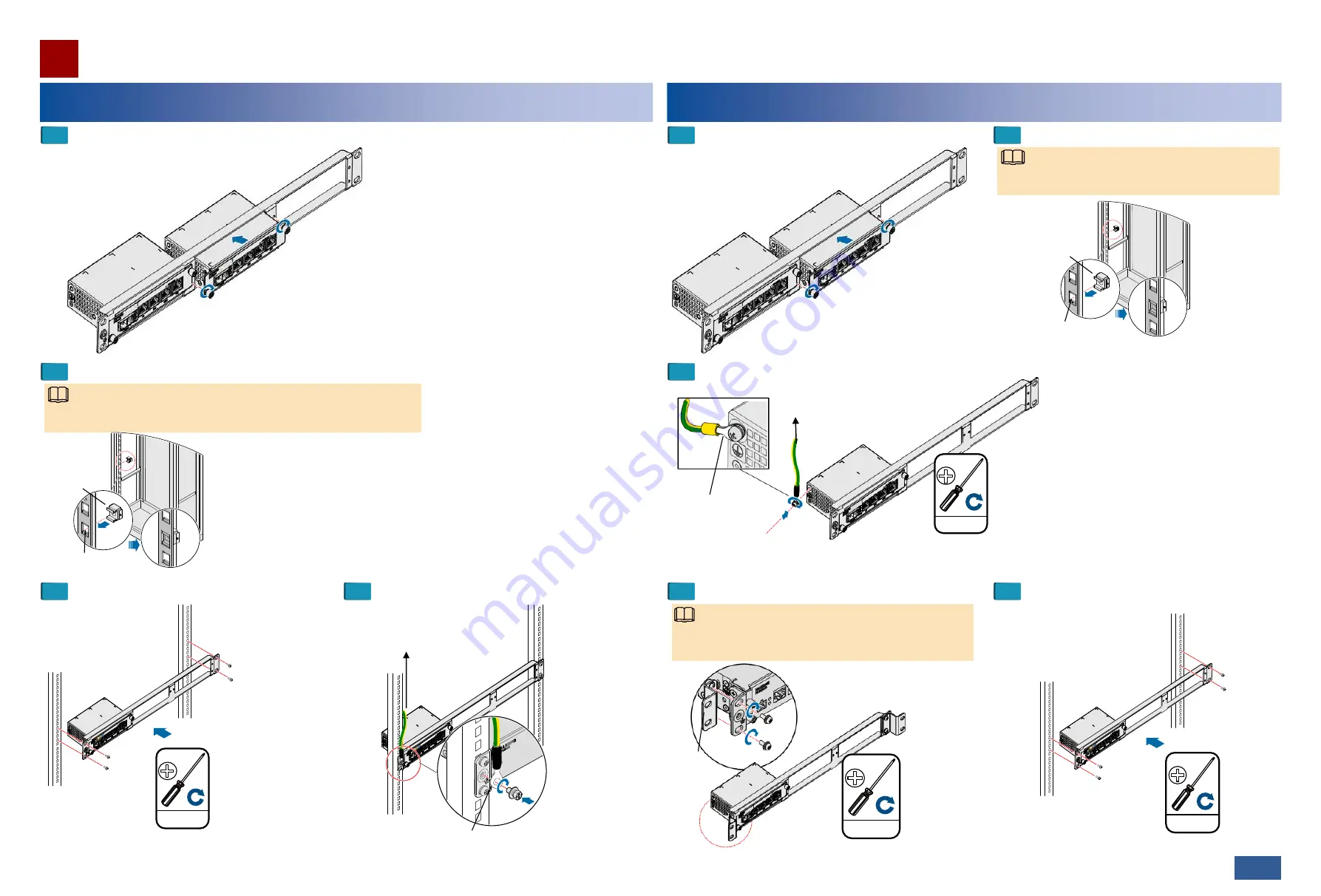
Installing  the PI in an ETSI Cabinet

Installation Guide

26/27 >>

When you fix the floating  nuts, allow  a heat dissipation  space of at 
least 25 mm above  and below  the PI.

Floating  nut

2.0

±

0.2  N·M

M6

Attach the PGND  cable  to a 
ground  point on a cabinet  column 
or to an indoor  ground  bar.

Install the PGND  cable  with the ground  screw (M4).

Mounting  hole

Attach the PGND  cable  to a ground  point 
on a cabinet  column or  to an  indoor 
ground  bar.

Install the PGND 
cable with  the ground 
screw (M4).

1.4

±

0.14  N·M

M4

Mounting 

ears

Before  installing the chassis in an ETSI  cabinet, adjust the 
holes for  installing  mounting  ears based  on the cabinet  type.

3.0

±

0.3  N·M

M6

2.0

±

0.2  N·M

M6

NOTE

NOTE

Installing  the PI in a 19-Inch Cabinet

Insert  the PI into a slot on  the auxiliary mounting  bracket and  tighten the 
captive  screws on the mounting  ears.

1

2

Fix the floating  nuts.

3

4

Install the chassis in the cabinet.

Install the PGND  cable.

Insert  the PI into a slot on  the auxiliary mounting 
bracket and  tighten the captive  screws on the 
mounting  ears.

1

3

Install the PGND  cable.

Mounting  hole

Floating  nut

When you fix the floating  nuts, allow  a heat dissipation 
space of  at least 25 mm above  and  below  the PI.

NOTE

2

Fix the floating  nuts.

4

5

Install the mounting  ears.

Install the chassis in the cabinet.

06

Содержание PI-DC A11

Страница 1: ...es Co Ltd Copyright Huawei Technologies Co Ltd 2018 All rights reserved 01 Safety Precautions Always hold an insulated part of the P E cable Never touch the RJ45 connector Do not touch the pins inside the P E port on the PI with your hands or a conductor Be sure to connect the power cables of the PI correctly to the positive and negative terminals of the power supply device To prevent damage to po...

Страница 2: ...B Port Description The GE electrical port is compatible with an FE electrical port and supports the MDI MDI X and auto MDI MDI X modes Pin Description 1 BGND 2 BGND 3 48 V power signal 4 BGND 5 BGND 6 48 V power signal 7 48 V power signal 8 48 V power signal Whether the P E ports use MDI or MDI X mode to transmit Ethernet service signals does not affect the pin assignments for power signals Pin as...

Страница 3: ...ending on the power of the powered device For details see technical specifications Maximum distance between the PI and powered device CAUTION B Application Scenarios A Principles Mapping between powered device types and power supply modes 03 The RTN PI DC A11 can supply power to OptiX RTN 300 full outdoor microwave equipment series The power supply mode of the PI varies according to powered device...

Страница 4: ...Compliant with ETSI EN 301 489 4 Compliant with ETSI EN 300 386 Safety Passes CE certification Compliant with EN60950 22 Compliant with IEC60950 22 Compliant with IEC60950 1 Compliant with EN60950 1 Item Description Major reference standards Operation Compliant with EN 300 019 1 4 class 4 1 Transportation Compliant with ETSI EN 300 019 1 2 class 2 3 Storage Compliant with ETSI EN 300 019 1 1 class...

Страница 5: ...d outside the holes remove the cable and cut the wires Then strip and connect the cable again A line mustbe inserted in the center of a hole A line mustbe perpendicular to a hole A line mustbe inserted in the center of a hole 4 CAUTION Insert the power cable Hole 2 Inserta blue 48 V line into it Hole 1 Inserta brown black 0 V ground line into it Ensure that the positive and negative lines are corr...

Страница 6: ...s in an ETSI cabinet adjust the holes for installing mounting ears based on the cabinet type 3 0 0 3 N M M6 2 0 0 2 N M M6 NOTE NOTE Installing the PI in a 19 Inch Cabinet Insert the PI into a slot on the auxiliary mounting bracket and tighten the captive screws on the mounting ears 1 2 Fix the floating nuts 3 4 Install the chassis in the cabinet Install the PGND cable Insert the PI into a slot on...

Страница 7: ...g ears 1 3 4 Install the PI on the wall Install the PGND cable 2 Mark and drill holes in the wall Hold the PI up to the wall and mark the drilling positions Drill the holes and insert the fixing bolts The position of the holes should allow a heat dissipation space of at least 50 mm at both the top and bottom of the PI 8 Drilling positions Drill Ф8 holes to a depth of 52 to 60 mm 300mm Mounting ear...

Страница 8: ... NOTE Connect the RJ45 connector to the GE port of the PI Black 0 V power cable connected to the positive terminal of the power supply device Install the P E cable of the PI Install the power cable of the PI Power on the device 1 Turn the power output switch on the rear of the PI to the FORCE side 2 Switch on the power supply device connected to the PI NOTE In normal conditions DC IN and P E OUT i...

Отзывы: