background image

16

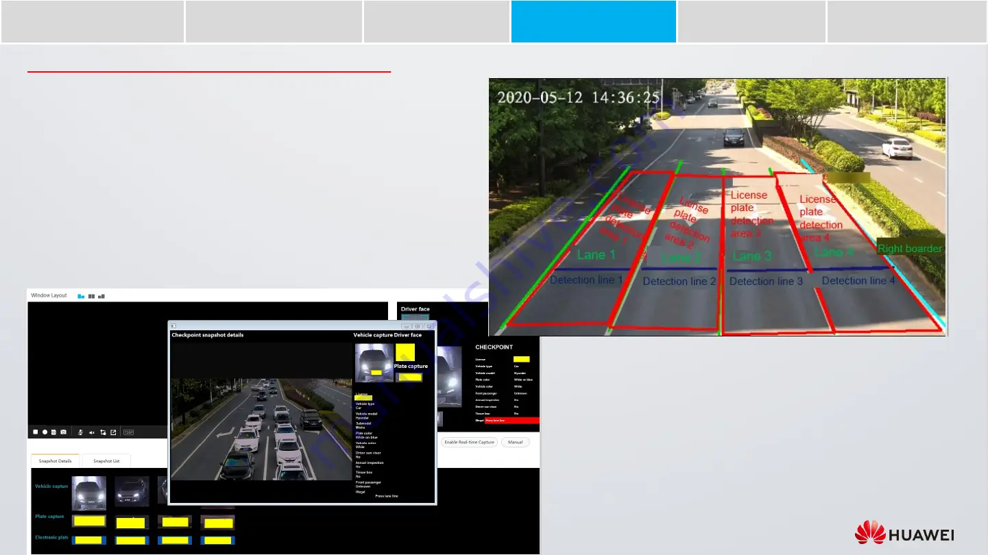
1. Draw detection lines and license plate recognition areas as required. The figure on 

the right shows an example.

For the camera web system of the 9.0.0.SPC6

xx

version, choose 

Settings

ITS 

Configuration

Application

, and click the 

Scene Configuration

tab.

For the camera web system of versions earlier than 9.0.0.SPC600, choose 

Intelligent Transportation

Scene Configuration

.

2. Set external device parameters as required. For example, set the parameters of loop 

vehicle detectors and radar detectors.

For the camera web system of the 9.0.0.SPC6

xx

version, choose 

Settings

ITS 

Configuration

Application

, and click the 

External Devices

tab.

For the camera web system of versions earlier than 9.0.0.SPC600, choose 

Intelligent Transportation

External Device

.

3. Go to the 

View

or 

Traffic Snapshots

page and click 

Enable Real-time Capture

or 

Manual

. The camera will then start detecting and taking snapshots, while real-time 

results are displayed on the right of and below the video pane.

Configure External Devices and Scenes

Search for and Log In 

to a Camera

Adjust the 

Camera Focus

Configure 

Checkpoint  Services

Adjust Camera Angles

Set Illuminator 

Parameters

Commission  the 

Radar Detector

Содержание ITS

Страница 1: ...Quick Guide to Huawei ITS SDC Site Survey and Commissioning Radar Detector Checkpoint Scenario ...

Страница 2: ... 12 20 V2 1 Updated flash light images and changed strobe lights to direct light sources 2020 03 16 V2 3 Modified lens installation descriptions 2020 06 08 V2 4 Added descriptions about smart LED illuminators and super low light checkpoint cameras 2021 04 22 V2 5 Added descriptions about three in one intelligent traffic illuminators super low light checkpoint cameras 2 0 and laser pointer based co...

Страница 3: ...ario Requirements Install Illuminators 04 Adjust the Illuminator Light Spot 01 02 03 Commissioning Search for and Log In to a Camera Adjust Camera Angles Adjust the Camera Focus 04 Configure Checkpoint Services 05 Configuring Illuminators 06 Troubleshooting 07 Commission the Radar Detector 05 Install and Adjust Radar Detectors ...

Страница 4: ...s on the base Note To use P Iris for a super low light checkpoint camera select a Huawei certified P Iris lens Connect to the IRIS port when installing an auto iris lens Guide rail 2 Adjust the camera s aperture for optimal image brightness Loosen the screw on the aperture ring and adjust the aperture to F1 8 to F2 2 Use a flat head screwdriver to tighten the screw on the side of the lens Adjust t...

Страница 5: ...from the intersection in a location where there are fewer lanes to facilitate license plate capture and recognition Avoid capturing bus stations in the camera view Vehicles may occlude each other at bus stations which affects license plate capture and recognition If there are street lamps and other light sources at the test site avoid sodium lamps and strobe or flash lights that are not controlled...

Страница 6: ...is document uses an X2391 20 T camera as an example A 9 megapixel super low light checkpoint camera has four groups of RS 485 ports D1 D1 D2 D2 D3 D3 and D4 D4 Both three in one intelligent traffic illuminators or smart LED illuminators and radar detectors need to connect to RS 485 ports In three lane or four lane detection schemes three radar detectors are used to measure vehicle speed and three ...

Страница 7: ...hicle target and the parallel distance line Adjust the Lens Install Illuminators Adjust the Illuminator Light Spot Determine Scenario Requirements Install and Adjust Radar Detectors Two Lane Detection by Super Low Light Checkpoint Camera Radar Detector Checkpoint in Main Lanes of Highways with 50 mm Lens ...

Страница 8: ...from the pole Adjust the Lens Install Illuminators Adjust the Illuminator Light Spot Determine Scenario Requirements Install and Adjust Radar Detectors Two Lane Detection by Super Low Light Checkpoint Camera Large sized High speed Vehicles Occupying Lanes with 20 mm Lens ...

Страница 9: ... cameras can only identify levels ranging from 0 V to 5 V Actual cables may vary Please refer to the device label If the signal control cable of the illuminator is not clearly identified as a level output or a Boolean value cable check the illuminator instructions or consult the illuminator supplier to confirm the signal control cable type Waterproof and insulate the pigtail cables to prevent wate...

Страница 10: ...ables may vary Please refer to the device label Waterproof and insulate the pigtail cables to prevent water from entering the device For details see the Quick Start Guide delivered with the camera The smart LED illuminator is an integrated strobe flash light and is used with super low light checkpoint cameras The following figure and table show the appearance cable connections and schematic diagra...

Страница 11: ...how the appearance cable connections and schematic diagram of the SS smart LED illuminator Note Two groups of control signal cables need to be connected RS 485 signal cables are connected to optimize the illuminator brightness Actual cables may vary Please refer to the device label Waterproof and insulate the pigtail cables to prevent water from entering the device For details see the Quick Start ...

Страница 12: ...t traffic illuminator is a three in one xenon LED integrated strobe flash light and is used with super low light checkpoint cameras The following figures and table show the appearance cable connections and schematic diagram of such illuminators Note Three groups of control signal cables need to be connected RS 485 signal cables are connected to optimize the illuminator brightness Actual cables may...

Страница 13: ...220 V live Blue 220 V neutral Yellow green GND earth Signal control cable Red Connects to the positive Boolean value terminal for example F1 of the camera Black Connects to the negative Boolean value terminal for example F1 of the camera Purple Connects to terminal A for example D1 of the camera s RS 485 port Blue Connects to terminal B for example D1 of the camera s RS 485 port Brown Connects to ...

Страница 14: ...ght and capture direction vehicle driving direction For example if the installation height is 6 m and the capture distance is 24 m the tilt angle for capturing approaching vehicles is 14 Power cable RS 485 cable Installation Height Distance from the Ground Tilt Angle α Approaching Vehicles Tilt Angle α Leaving Vehicles Capture Distance 5 m 14 17 15 30 m 6 m 14 18 15 30 m 7 m 15 18 15 30 m 8 m 16 2...

Страница 15: ...ss 4 Open Internet Explorer as an administrator and enter the default camera IP address in the address box 6 Configure text overlay on the image Choose Settings Video Audio Image OSD Click Add OSD or the edit icon in the Operation column and add the camera installation location to the Content column as shown in the following figure 5 Change the IP address of the camera as planned Choose Settings N...

Страница 16: ... image The horizontal resolution of the license plate of a vehicle parked at the capture position is at least 120 pixels For urban roads with regulated vehicle speed less than 80 km h the capture position namely the detection line is 25 m away from the pole 13 Place a cone 25 m away from the pole Urban road vehicle speed 80 km h About 25 m away from the pole Search for and Log In to a Camera Adjus...

Страница 17: ... camera if you know the optical zoom ratio To check the optical zoom ratio choose Settings System Visible Area in the camera web system click Lens Info and check the value of Optical zoom ratio If the focal length of an ITS camera ranges from 11 mm to 40 mm an optical zoom ratio of 1x indicates that the focal length is 11 mm 2x indicates that the focal length is 22 mm and so on The horizontal reso...

Страница 18: ...on items and click Save For the camera web system of the 9 0 0 SPC6xx version select Video based for Detection mode Dual shutter for Capture mode and Radar basedfor Speed measurement on the Violation Types and Lanes tab page For the camera web system of versions earlier than 9 0 0 SPC600 select Video based for Detection mode Dual shutter for Capture mode and Radar based for Speed measurement on th...

Страница 19: ...etectors For the camera web system of the 9 0 0 SPC6xx version choose Settings ITS Configuration Application and click the External Devices tab For the camera web system of versions earlier than 9 0 0 SPC600 choose Intelligent Transportation External Device 3 Go to the View or Traffic Snapshots page and click Enable Real time Capture or Manual The camera will then start detecting and taking snapsh...

Страница 20: ...djust the illuminatorangle to ensure that the light spot is close to the vehicle rear If the license plate is overexposed move the light spot to a position further away from the vehicle rear Note 1 When you adjust an illuminator you are advised to also disable the illuminators for other lanes When you adjust the angle of the illuminator the visibility of license plates may be affected You can adju...

Страница 21: ... For the camera web system of versions earlier than 9 0 0 SPC600 select External device for Detection mode and Radar based for Speed measurement on the Violation Type tab page 8 Adjust the radar triggering distance based on the vehicle capture quality The triggering distance of radar detectors used for measuring vehicle speed is generally less than 30 m 7 Set parameters such as the triggering dist...

Страница 22: ... level indicates fewer noises but blurrier images A lower spatial noise reduction level indicates clearer images but more noises Lower the spatial noise reduction level 1 Choose Settings Video Audio Image Image and click Image Enhancement 2 Set Denoising to Expert mode 3 Decrease the value of Spatial denoising level Increase the sharpness 1 Choose Settings Video Audio Image Image and click Image A...

Страница 23: ...s unsatisfactory increase the exposure compensation coefficient Enable license plate brightness compensation 1 For the camera web system of the 9 0 0 SPC6xx version choose Settings ITS Configuration Snapshot and click IntelligentImage Enhancement For the camera web system of versions earlier than 9 0 0 SPC600 click the ITS application on the App Home page On the page displayed choose Intelligent T...

Страница 24: ... Decrease the gain limit 1 Choose Settings Video Audio Image Image and click Exposure 2 Decrease the value of Gain limit Decrease the exposure compensationcoefficient 1 Choose Settings Video Audio Image Image and click Exposure 2 Decrease the value of Exposure compensation coefficient The overall image brightness is normal but the license plate is too dark The possible cause is that the illuminato...

Страница 25: ...d operating results future product portfolio new technology etc There are a number of factors that could cause actual results and developments to differ materially from those expressed or implied in the predictive statements Therefore such information is provided for reference purpose only and constitutes neither an offer nor an acceptance Huawei may change the information at any time without noti...

Отзывы: