FusionModule1000A40 ICT Solution
Maintenance Guide
4 Parts Replacement
Issue 01 (2019-03-05)
Copyright © Huawei Technologies Co., Ltd.
92
Follow-up Procedure
Dispose of the removed air cooled in-row precision air conditioner that is confirmed faulty.
4.2.3 Replacing a Remote T/H Sensor for an Air Conditioner
Prerequisites
A spare T/H sensor of the same model is available and functional.
Impact on the System
None
Preparations
Tool: flat-head screwdriver, step ladder (2 m)
Material: spare remote T/H sensor
Documents: remote T/H sensor DIP switch initial configuration table
Skill requirement: cooling engineer
For the table, see the initial configuration parameter manual for the solution in use.
Procedure
Step 1
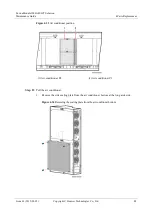
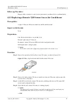
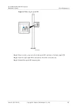
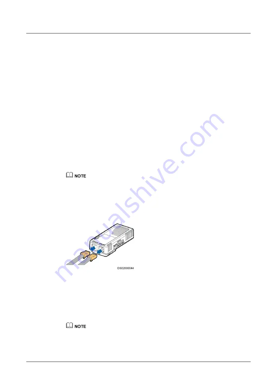
Remove the network cable from the remote T/H sensor, as shown in Figure 4-39.
Figure 4-39
Removing the network cable from the remote T/H sensor
Step 2
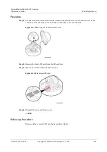
Remove the faulty remote T/H sensor, install a new remote T/H sensor, and reconnect the
network cable to the sensor.
Step 3
Set the DIP switch for the remote T/H sensor by referring to the remote T/H sensor DIP
switch initial configuration table.
Step 4
Check that the new remote T/H sensor is working properly.
If the indicator of the remote T/H sensor is on and the air conditioner LCD does not display any
communication failure alarm, the remote T/H sensor is working properly.
----End

