FusionModule1000B Air-Cooled IT Solution
Maintenance Guide
6 Parts Replacement
Issue 02 (2017-01-10)
Huawei Proprietary and Confidential
Copyright © Huawei Technologies Co., Ltd.
102
Documents: documents delivered with the GSM modem, management system initial
configuration table, monitoring device layout
Skill requirement: weak-current engineer
For the diagrams and tables, see the initial configuration parameter manual for the solution in use.
Procedure
Step 1
Shut down the GSM modem, and unplug the power cable.
Step 2
Remove the GSM modem serial cable from the serial port of the RH2288 server.
Step 3
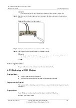
Remove the GSM modem antenna.
Step 4
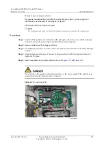
Remove the faulty GSM modem, and install the new GSM modem using a Phillips
screwdriver.
Step 5
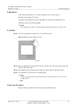
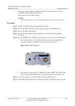
Remove the SIM card from the faulty GSM modem and insert it in the new GSM modem.
1.
Press the yellow button on the faulty GSM modem using a small-sized flat-head
screwdriver, and remove the SIM card, as shown by (1) in
Figure 6-20
Removing the SIM card
2.
Press the yellow button on the new GMS modem, place the SIM card inside the SIM
card tray, and push the SIM card tray into the slot, as shown by (2) in
Step 6
Connect the serial port of the GSM modem to that of the RH2288 server.
Step 7
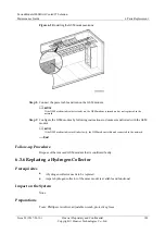
Reinstall the GSM modem antenna, and bind the antenna to the cable tray using cable ties.

