background image

Introduction

1

3

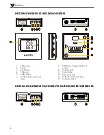
HE500V5/HE500V10/HE500M/HE500N

HE500A-EX/HE500V5-EX/HE500V10-EX/HE500M-EX/HE500N-EX

3

2

4 5 6

7

8

RANGE:-30~70

/0~100%RH

SN:

HUATO SYSTEM CO.,LTD

HE500A2138

MODEL:HE500A-EX


1.

2.

3.

4.

5.

6.

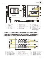
LCD screen

Label

Set button

Value up

Value down

Confirm button (save set 

data)

Stabilizer of upper and lower 
covers

Venting hole

Screw holes

Threading hole

Collection of Thread hole

Connection Port

7.

8.

9.

10.

11.

12

3

2

4 5 6

7

8

RANGE:-0~50

/0~100%RH

SN:

HUATO SYSTEM CO.,LTD

HE500A2138

MODEL:HE500V5

1

10

9

9

11

12

Содержание HE500 Series

Страница 1: ...User sGuide HE500 Series Temperature Humidity Transmitter wall mounted E mail sales huato com Talk to our sales and shop online at www huato cn...

Страница 2: ...t notice www huato cn sales huato com HUATO HUATO ELECTRIC CO LTD Toll Free 0755 29977605 Customer Service 0755 29977605 Engineering Service 0755 29977605 Fax 86 755 29748856 E mail sales huato com He...

Страница 3: ...2 1 6 Temperature and Humidity Data Logger Screen 3 1 7 Button function instructions 5 1 7 1 Button function instructions 5 1 7 2 HE500A button operation instructions 5 1 7 3 HE500M N button operatio...

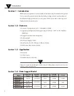
Страница 4: ...ed for faster heat dissipation Wall mounted DC Power Supply 9 30V Host Size L x H x D 100mm x 100mm x 30mm LCD Screen Size 60mm x 40mm Section 1 3 Application Museums Archive room Industrial and civil...

Страница 5: ...A TH HE500A EX HE500V5 HE500V5 EX HE500V10 HE500V10 EX HE500M HE500M EX HE500N HE500N EX HE500A TH 1 2 3 4 5 6 LCD screen Label Set button Value up Value down Confirm button save set data Stabilizer o...

Страница 6: ...O LTD HE500A2138 MODEL HE500A EX 1 2 3 4 5 6 LCD screen Label Set button Value up Value down Confirm button save set data Stabilizer of upper and lower covers Venting hole Screw holes Threading hole C...

Страница 7: ...e unit symbol Section 1 6 Temperature and Humidity Data Logger Screen HE500A TH HE500A EX HE500V5 HE500V5 EX HE500V10 HE500V10 EX HE500M HE500M EX HE500N HE500N EX 1 2 3 4 5 LCD screen Label Set butto...

Страница 8: ...emperature SET mode The basic flow of the HE500A setting interface is Temperature deviation value setting humidity deviation value setting C F switching setting 1 HE500A power on display instructions...

Страница 9: ...tton to stop accumulating reduced The display interface is shown in Figure 4 Figure 4 Figure 5 3 Humidity deviation setting After setting the temperature deviation value press the MENU key again to se...

Страница 10: ...High Alarm Setting Humidity under low alarm setting alarm switch setting temperature and humidity deviation value setting The basic flow of the HE500N setting mode is C F switching setting over temper...

Страница 11: ...reduced the address value is greater than zero less than 255 3 Baud rate setting HE500M Press the MENU button again to display the screen display content as shown in Figure 5 2 Baud rate setting Pres...

Страница 12: ...shown in Figure 10 the LCD screen will display the setting temperature SET and the setting item C At this time the default temperature symbol is C then press UP DOWN button can be used to switch betw...

Страница 13: ...the button to stop accumulating reduced until the user The value you want to set Figure 1 5 The temperature is too high alarm settings Press the MENU button again the interface will display as shown...

Страница 14: ...ced release the button to stop the accumula tion reduced until the user The value you want to set Figure 13 8 humidity is too low alarm settings Press the MENU button again the interface will display...

Страница 15: ...umulating reduced until the user wants to set the value Figure 18 Figure 17 9 temperature and humidity is too high and too low alarm settings Press the MENU button again the interface will display as...

Страница 16: ...5V 4mA 20mA 4mA 20mA 0 5V 0 10V 0 10V Output Type 0 5V 0 10V 4 20mA 0 30 100 RH 50 70 Introduction 1 13 11 Restore factory settings HE500M Press MENU again to enter the factory reset interface After p...

Страница 17: ...Temperature Output Humidity Output Positive DC Input Installation and Instruction 2 Section 2 Method of Cable Installation Section 2 1 Voltage Section 2 2 Current This section describes the installati...

Страница 18: ...A B Gnd Vcc 1 2 5 6 485 485 Negative DC Input Positive DC Input Section 2 3 Modbus RS485 Installation and Instruction 2 15...

Страница 19: ...nstallation and Instruction 2 8 Bits 8 Bits N x 8 Bits 16 Bits Address Function Data Check Section 2 4 Installation Size Section 2 5 Standard MODBUS RTU Data Frames Modbus 70mm 70mm 67mm 5mm 8mm 4mm 1...

Отзывы: