17
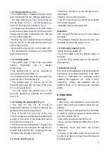
7.3.1. Stop height
(Fig. 9-13)
•
The parallel stop
(7)
supplied with the bench-
type circular saw has two different guide faces.
•
For thick material you must use the stop rail
(23)
as shown in
Fig. 11,
for thin material you
must use the stop rail as shown in
Fig.10.
•
To change over the stop rail
(23)
to the lo-wer
guide face you have to slacken the two knurled
screws
(26)
in order to disconnect the stop rail
(23)
from the holder
(24).
•
Remove the two knurled screws
(26)
through
the one slot
(27)
in the stop rail
(23)
and in-sert
in the other slot (25).
•
Remount the stop rail
(23)
on the holder
(24)
.
•
The procedure for changing over to the high
guide face is similar.
7.3.2. Cutting width:
•
The parallel stop
(7)
has to be used when
making
longitudinal
cuts
in
wooden
workpie-ces.
•
The parallel stop
(7)
can be mounted on
eit-her side of the saw table
(1).
•
The parallel stop
(7)
has to be mounted in the
guide rail
(28)
of the saw table (1).
•
The parallel stop
(7)
can be set to the
requi-red dimension with the help of the scale
(22)
on the guide rail
(1)
.
•
You can clamp the parallel stop in the
requi-red position by pressing the eccentric
lever
(12)
.
7.3.3. Setting the stop length
(Fig. 9)
•
The stop rail
(23)
can be moved in
longitudi-nal direction in order to prevent the
workpiece from becoming jammed.
•
Rule of thumb: The rear end of the stop
co-mes up against an imaginary line that begins
roughly at the center of the blade and runs at
an angle of 45
°
to the rear.
•
Set the required cutting width - Slacken the
knurled screws
(26)
and push the stop rail
(23)
forward until it touches the imaginary 45
°
line.
- Retighten the knurled screws
(26)
.
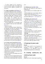
7.4. Cross stop
(Figure 8)
•
Slide the cross stop
(14)
into the groove
(21)
of the table.
•
Slacken the knurled screw
(20)
.
•
Turn the cross stop
(14)
until the arrow points
to the angle required.
•
Retighten the knurled screw
(20)
.
Important!
•
Do not push the stop rail
(23)
too far toward
the blade.
•
The distance between the stop rail
(23)
and
the blade
(4)
should be approx. 2 cm.
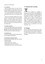
7.5. Setting the angle
(Fig. 14)
•
Undo the fixing handle
(9)
.
•
Turn the handle to set the desired angle on
the scale.
•
Lock the fixing handle again in the required
angle position.
7.6 Overload cut-out
The motor of this appliance is protected against
overload by an overload switch
(B).
If the rated
current is exceeded, the overload switch
switches the appliance o
ff
. After a short
cooling-o
ff
phase, the appliance can be
switched back on by pres-sing the overload
switch.
8. Operation
Warning!
•
After every new adjustment we recommend
you to make a trial cut in order to check the new
settings.
•
After switching on the saw, wait for the blade
to reach its maximum speed of rotation before
commencing with the cut.
•
Take extra care when starting the cut!
•
Never use the equipment without the suction
function.
•
Regularly check and clean the suction
chan-nels.
•
The cap on the blade guard can be removed
in order to be able to connect a suction hose to
the blade guard.


