lp-666 Rev. 003 Rel. 001 Date 2.25.20
57
Installer #
Description
Detail
37
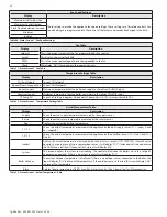
Modbus Mode
Enables Modbus/BACnet Mode on the appliance. Factory Default: OFF (Range: ON, OFF, AUTO).
See Modbus/BACnet Instructions (lp-548) for details.
NOTE: Turning this Mode “ON” without
a connected and powered Modbus communication adapter (p/n 7350P-629) will result in
improper appliance operation.
Service calls associated with this ARE NOT covered by warranty.
38
Modbus Address
Sets the Modbus/BACnet address. The address space is comprised of 256 addresses. These are
defined as follows:
• Address 0 is a broadcast address. The master can send data to address 0 and all followers will
process the data.
• Addresses 1 – 247 are free to be assigned to Modbus devices on the bus. Each address can be
assigned to only one Modbus device on the bus.
• Addresses 248 – 256 are not available for use.
39
Baud Rate
The baud rate (communication speed) can be set on the control display to either 9600 or 19200
baud. All HTP appliances, as well as any other device on the same bus and the Modbus/BACnet
master, must have the same baud rate setting. Select the highest baud rate that offers the most
reliable communication performance over the bus.
40
Parity
NOTE:
This setting only applies to Modbus operation. The BACnet protocol does not utilize parity
for communication and this setting will have no effect.
The parity/stop bits parameter of the Modbus/BACnet adapter must match the rest of the devices
on the bus. Although it is common to set serial devices to use no parity, setting the parity to even
or odd may improve communications reliability on all connected devices on the bus.
The following information details the
0-10V Output
parameters described in Function 56 that can be read at a Building Management System.
BOIL POWER
- 0-10V output is proportional to boiler firing rate. 0V = Not Firing, 1.5V = Minimum Firing Rate, 10V = Maximum Firing Rate
CASC POWER
- When configured on the Cascade Master, 0-10V is proportional to the firing rate of the Cascaded System. 0V = Not Firing, 1.5V
= Minimum Firing Rate (One Boiler Lit), 10V = Maximum Firing Rate of all Connected Boilers
FAN SPEED
- Output is proportional to boiler fan speed. 0V = Fan is Off, 1.5V = Minimum Fan Speed, 10V = Maximum Fan Speed
ALARM
- 0V = Alarm is Off, 10V = Alarm is On
TEMPERATURE
- Output follows boiler temperature setting based on outdoor reset. 0V = Minimum Boiler Temperature for Maximum Outdoor
Temperature Setting. 10V = CH (or cascade) temperature setting. This number will vary with the outdoor temperature so that the user can
know what setpoint temperature the boiler is trying to achieve.
FLAME
- Equals boiler Flame Current. 0V = 0ua, 10V = 10ua.
PUMP
- This output controls CH pump speed to maintain the desired Delta T. 0V = OFF, 2V (or output offset value greater than 2) = Minimum
Pump Speed, 10V = Maximum Pump Speed.
NOTE:
Modbus Mode must be enabled on the appliance as outlined above for the following parameters to be viewed and changed.
54
Boost Time
(Same Value as the
Boost Slider in the
Outdoor Reset Screen)
Temporarily overrides the Outdoor Reset Curve to bring the boiler up to the maximum setpoint
to satisfy a thermostat call in less time. Factory Default: 0 min (Range: 0-762 min in increments of
6 minutes.) EXAMPLE: If 6 minutes is selected, and there has been a call for heat for 6 minutes, the
boiler will override the Outdoor Reset Curve and boost to the maximum setpoint until the call for
heat is satisfied. The boiler setpoint will stay at max for 6 additional minutes after the thermostat
opens before returning to the Outdoor Reset Curve.
55
CH Pump Priority
NOTE:
This function applies only to boilers with a Cascade Address of 0.
Controls whether the CH pump will meet a call for heat while also meeting or answering a DHW
call. A setting of OFF will not run the CH pump while running the DHW pump; an ON setting will
run the CH pump while simultaneously running the DHW pump. Factory Default: OFF (Range ON
/ OFF)
56
OA1 Configuration
Controls the operation of the 0-10V A output on the Field Connection Board. Factory Default:
BOIL POWER (Range: BOIL POWER / CASC POWER / FAN SPEED / ALARM / TEMPERATURE / FLAME
/ PUMP).
NOTE:
The following parameters are displayed regardless if Modbus Mode is enabled.
57
OA1 Offset
This value is added to the OFFSTATE VOLT OA1 value, to determine the total voltage output
required at the minimum case. Factory Default: 1.5 (Range: 0.0 to 9.9)
58
OB1 Configuration
Controls the operation of the 0-10V B output on the Field Connection Board. Factory Default:
BOIL POWER (Range: BOIL POWER / CASC POWER / FAN SPEED / ALARM / TEMPERATURE / FLAME).
59
OB1 Offset
This value is added to the OFFSTATE VOLT OB1 value, to determine the total voltage output
required at the minimum case. Factory Default: 1.5 (Range: 0.0 to 9.9)
60
CH dT Setting
This parameter is only available when PUMP is selected in Function 56. Determines the desired
temperature difference between the SUPPLY and RETURN temperatures. Factory Default: 19F
(Range: 0 - 47F)
61
Offstate Voltage OA1
This parameter is only available when PUMP dT is selected in Function 56. Determines the voltage
present in OA1 when the pump is supposed to be OFF. Factory Default: 0.0 (Range: 0.0 to 9.9)
Table 17 - System Setting Program Navigation

