


lp-666 Rev. 003 Rel. 001 Date 2.25.20
73
g.
i. For 400 - 500 Models: Loosen the band clamp from the air intake
assembly. Then pull the entire combustion assembly towards you,
while removing or pushing aside any wiring to allow removal of
the assembly. Set aside in a safe location for eventual reinstallation.
ii. For 650 - 1000 Models: Pull the entire combustion assembly
towards you and then down to disconnect from the air intake
assembly. Then remove or push aside any wiring to allow
removal of the assembly. Set aside in a safe location for eventual
reinstallation.
iii. For 1500 - 2000 Models: First, remove the five (5) screws
attaching the cabinet post to the left side of the boiler cabinet
assembly. Then remove the post.
Then remove the three (3) screws attaching the air intake assembly.
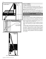
The heat exchanger features a hinged sliding device to ease
service. First remove the pin located to the left of the door. This
locks the hinge in place. After the pin is removed the door will
swing at the hinge, providing better access to the inside of the
heat exchanger. BE CAREFUL NOT TO DAMAGE THE COMBUSTION
ASSEMBLY, WHICH IS MOUNTED TO THE DOOR, WHEN OPENING
AT THE HINGE.
After the pin is removed: (1) Lift the air intake pipe. (2) Spin air
intake pipe while sliding the combustion assembly out. (3) Swing
the assembly open to allow access to the combustion chamber.
(4) Slide the assembly back toward the heat exchanger and use
the removed pin to secure in the open position while performing
maintenance. See Figure 57.
WARNING
!
Do not use solvents to clean any of the burner components. The
components could be damaged, resulting in unreliable or unsafe
boiler operation, substantial property damage, severe personal
injury, or death.
4
2
1
6
3
5
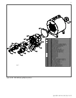
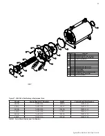
Figure 56 - 400 - 1000 Model Heat Exchanger Detail - Burner Door Torque
Sequence
1
2
3
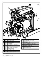
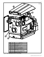
Figure 57 - 1500 - 2000 Model Heat Exchanger Detail - Sliding Out the Combustion Assembly
2. Spray the coils liberally with the FDA approved liquid lime scale
remover. Confine the spray to the area being cleaned. Avoid getting
the ceramic target wall wet. If the condensate system is blocked, use
a vacuum to clear it.
3. Scrub coils of any buildup
with a nylon, stainless steel, or
brass brush. Do not use a steel
brush. Vacuum the debris from
the coils.
4. Spray the coils again with
clear tap water. Confine
the spray to the area being
cleaned. Flush the combustion
chamber with fresh water
until it runs clear from the
condensate reservoir. At this
point, the boiler should be
ready to be reassembled.
a. Inspect gaskets.
b. Reinstall the combustion
assembly.
c. Reinstall and tighten the
bolts to the burner plate
using staggered tightening
sequence. See Figure 56.
d. Reconnect all wiring
connections.
e. Use pipe dope or tape to
reconnect the flex line to
the gas valve. (IMPORTANT: CHECK FOR GAS LEAKS!)
f. Reinstall the air intake.
g. Restore gas and power to the boiler.
h. Turn boiler power on and create a heat demand. When boiler is
lit observe condensate flow from the boiler. Be sure the boiler is
operating properly.
i. Reinstall the condensate trap cleanout trap.