


lp-666 Rev. 003 Rel. 001 Date 2.25.20
17
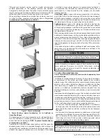
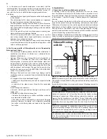
2. The expansion tank must be located as shown in Applications, this
manual, or following recognized design methods. See expansion tank
manufacturer’s instructions for details.
3. Connect the expansion tank to the air separator only if the separator
is on the suction side of the circulator. Always install the system fill
connection at the same point as the expansion tank connection to the
system.
4. Most chilled water systems are piped using a closed type expansion
tank.
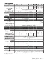
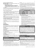
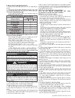
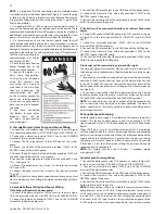
Table 4 - Heat Exchanger Volume
E. Circulators
SIZING SPACE HEAT SYSTEM PIPING
Size the piping and components in the space heating system using
recognized design methods.
CAUTION
DO NOT
use the boiler circulator in any location other than the
ones shown in this manual. The boiler circulator location is selected
to ensure adequate flow through the boiler. Failure to comply with
this caution could result in unreliable performance and nuisance
shutdowns from insufficient flow.
F. Hydronic Piping with Circulators, Zone Valves, and
Multiple Boilers
The boiler is designed to function in a closed loop hydronic system.
The included temperature and pressure gauge allows the user to
monitor system pressure and outlet temperature from the boiler. It is
important to note that the boiler has a minimal amount of pressure
drop that must be calculated when sizing the circulators. Each boiler
installation must have an air elimination device that will remove air
from the system.
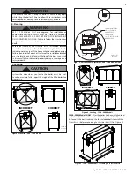
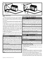
Install the boiler so the gas ignition system components are protected
from water (dripping, spraying, etc.). Allow clearance for basic service of
the boiler circulator, valves, and other components. Observe minimum
1” clearance around all uninsulated hot water pipes when openings
around pipes are not protected by non-combustible materials.
On a boiler installed above radiation level, some states and local codes
require a low water cut off device. This is provided standard on the
boiler. Check with local codes for additional requirements. If the boiler
supplies hot water to heating coils in air handler units, flow control
valves or other devices must be installed to prevent gravity circulation
of boiler water in the coils during the cooling cycle. Chilled water
medium must be piped in parallel with the boiler.
Freeze protection for new or existing systems must use glycol
specifically formulated for this purpose. This glycol must include
inhibitors that will prevent it from attacking metallic system
components. Make certain that the system fluid is checked for the
correct glycol concentration and inhibitor level. The system should be
tested at least once a year and as recommended by the producer of the
glycol solution. Allowance should be made for the expansion of the
glycol solution in the system piping. Example: 50% by volume glycol
solution expands 4.8% in volume for the temperature increase from
32
o
F to 180
o
F, while water expands 3% over the same temperature rise.
CAUTION
Never use dielectric unions or galvanized steel fittings when
connecting to a stainless steel storage tank or boiler. Failure to
follow this instruction can lead to premature failure of the boiler
system. Such failures ARE NOT covered by warranty.
The boiler should not be operated as a potable hot water heater.
The boiler should not be used as a direct hot water heating
device.
Model
Heat Exchanger Volume (Gallons)
400
3.8
500
4.3
650
5.6
800
6.6
1000
8.1
1500
12.9
2000
16.25