
B 215 / B 225 Evo
Operator’s manual
97
UK
10 Perform a test wheel spin to check the balancing accuracy.
The rim surface must be perfectly clean to make the weight stick efficiently to the rim. If
necessary, clean the surface using suitable cleansing products.
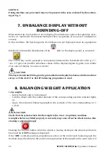
• Manually applied adhesive weights
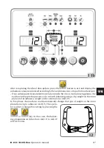
1 Select the first side to be balanced
2 Turn the wheel until the central element of the corresponding position indicator lights
up.
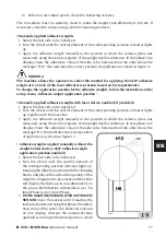
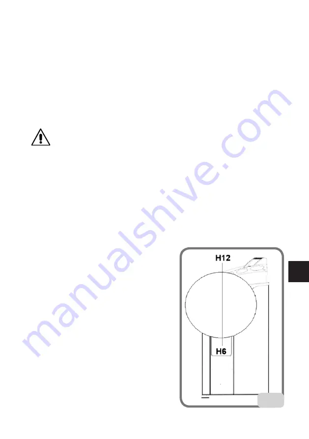
3 Apply the adhesive weight manually in the position in which the relative plane was
measured, using the centre of gravity of the weight itself as reference. In this phase, one
display shows the unbalance value of the side to be balanced and the other shows the
message "H.12" that indicates the correct position of application as shown in figure 19.
WARNING
The machine allows the operator to select the method for applying the CLIP adhesive
weight at 6 o'clock (if the laser indicator is present) based on his requirements.
To change the application position for the adhesive weights, follow the instructions in the
set up menu "Adhesive weight application position ”.
• Manually applied adhesive weights with laser device enabled (if provided)
1 Select the first side to be balanced.
2 Turn the wheel until the central element of the corresponding position indicator lights
up together with the laser line.
3 Apply the adhesive weight manually in the position in which the relative plane was
measured, using the centre of gravity of the weight itself as reference. In this phase, one
display shows the unbalance value of the side to be balanced and the other shows the
message "H.6" that indicates the correct position
of application as shown in figure 19.
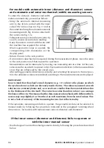
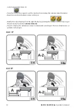
• Adhesive weights applied manually without the
weight-holder device (CLIP adhesive weight
application position enabled)
1 Select the first side to be balanced.
2 Turn the wheel until the central element of
the corresponding position indicator lights up.
Keeping the wheel in position with the clamping
brake, a display will now show the quantity of the
weight to be applied in gr/ounces and the other
will display the distance in mm alternatively to
the plane identification abbreviation (A-1 for
Inner Plane/A-2 for Outer Plane).
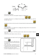
3
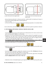
IN THE MACHINE VERSION WITH AUTOMATIC
SENSOR
move the sensor until it reaches the
indicated position. During this phase, the unbal-
ance value of the side to be balanced is shown
on one display, whereas the numerical value
updated according to the sensor position, which
19
Содержание B 215 Evo
Страница 63: ...128 B 215 B 225 Evo Operator s manual...
Страница 64: ...B 215 B 225 Evo Operator s manual 129 UK Notes...
Страница 65: ...130 B 215 B 225 Evo Operator s manual Notes...


