


2 How to Install and Replace Components In Your Desktop PC
Replacing a Power Protection Device
76
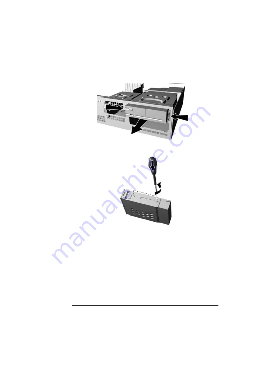
3
Press the two latches inward and slide out the device
.
4
Remove the power protection device from the tray by removing the
two retaining screws.
5
Attach the new device to the tray and secure it into position with the
two retaining screws.
6
Slide the device back into the PC.
7
Replace the power alert and passthru cables to the power protection
device, and to the power supply unit and system board.
Содержание Vectra VLi 8
Страница 10: ...10 English ...
Страница 118: ...3 How to Install and Replace Components In Your Minitower PC Installing a Security Cable 118 ...
Страница 130: ...4 Managing Your PC Master Pass Key System 130 ...
Страница 131: ...5 Technical Information ...
Страница 136: ...5 Technical Information Physical Characteristics 136 ...
Страница 137: ......


