background image


English

69

4   Troubleshooting Your PC

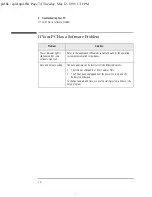
If You Cannot Turn Off Your PC

If You Cannot Turn Off Your PC

Problem

Check

How

PC makes a buzzing 
or beeping sound 
when you press the 
power button.

Whether the PC is in a 
suspend/sleep mode, in which 
case a “power off” would risk a 
loss of information/data.

Move the mouse or press a key to 
try to wake up the PC.

If you cannot wake up the PC, and 
you still cannot turn it off using the 
power button, unplug the PC from the 
power supply.

PC does 

not

 make a 

buzzing or beeping 
sound when you 
press the power 
button, but you are 
still unable to turn it 
off.

That you have saved all data and 
exited all programs. 

Save all data and exit all programs 
(if you can).

Press the power button and keep 
it pressed for 5 seconds. The PC 
will turn off.

spid.bk : spid-up4.fb4  Page 69  Tuesday, May 12, 1998  1:11 PM

Содержание Vectra VEC 7

Страница 1: ...HP Vectra VE Series 7 Upgrade and Maintenance Guide spid bk spiddtfc fb4 Page 1 Tuesday May 12 1998 1 11 PM ...

Страница 2: ... in connection with the furnishing performance or use of this material This document contains proprietary information that is protected by copyright All rights are reserved No part of this document may be photocopied reproduced or translated to another language without the prior written consent of Hewlett Packard Company Microsoft NT and Windows are U S registered trademarks of Microsoft Corporati...

Страница 3: ...Upgrade and Maintenance Guide spid bk title fb4 Page iii Tuesday May 12 1998 1 11 PM ...

Страница 4: ... PC Troubleshoot problems on the PC Find out where to get more information and support For information about setting up and using your PC refer to the User s Guide that came with your PC The User s Guide is also part of the MIS kit for your PC refer to page vi spid bk title fb4 Page iv Tuesday May 12 1998 1 11 PM ...

Страница 5: ... disconnected from the power by removing the power cord from the power outlet This means the PC must be located close to a power outlet that is easily accessible For your safety never remove the PC s cover without first removing the power cord from the power outlet and any connection to a telecommunications network Always replace the cover on the PC before switching it on again To avoid electric s...

Страница 6: ...bout installing accessories and troubleshooting Upgrade and Maintenance Guide this manual Familiarization Guide PC training information for support and maintenance personnel Network Administrator s Guide network driver installation information for network administrators Service Handbook Chapters information on upgrade and replacement parts including HP part numbers You will also find complete info...

Страница 7: ...tallation 9 Installing an IDE Hard Disk Drive in an Internal Shelf 10 Installing a CD ROM Tape or Zip Drive in a Front Shelf 13 Installing Accessory Boards 18 Installing an Accessory Board 19 Configuring Accessory Boards with Plug and Play 21 Configuring non Plug and Play ISA Accessory Boards 22 Installing a Security Cable 23 Changing the Battery 24 Installing a Key Lock 26 2 How to Install Access...

Страница 8: ...sk Drive in an Internal Shelf 37 Installing a Zip Drive CD ROM Drive or Tape Drive 40 Installing Accessory Boards 44 Installing an Accessory Board 45 Configuring Accessory Boards with Plug and Play 47 Configuring non Plug and Play ISA Accessory Boards 47 Installing a Security Cable 48 Changing the Battery 49 Installing a Key Lock 51 3 Security Features Setting Passwords 54 Using BIOS Passwords 54 ...

Страница 9: ...ere Is a Hard Disk or CD ROM Drive Test Error 64 If There Is a CMOS Test Error 65 If There Is a Serial or Parallel Port Test Error 66 Other Configuration Problems 67 If There Is a Beep Code During Startup 68 If You Cannot Turn Off Your PC 69 If You Have Forgotten Your Password 70 If the Wake On LAN Feature Does Not Work 71 If There Is an IRQ Problem Installing a Sound Board 72 If Your PC Has an Au...

Страница 10: ...and HP Software Components 77 Installation of Customer Specific Software 79 Recovering from a BIOS Update Failure 80 HP DiagTools 82 Setting the Device Boot Order 84 Technical Information 85 System Board Switches 85 Power Consumption 86 Acoustic Noise Emission 86 Physical Characteristics 87 IRQs DMAs and I O Addresses Used by Your PC 88 Hewlett Packard Support and Information Services 90 Index 91 ...

Страница 11: ...ccessories in Your Desktop PC This chapter explains in detail how to install accessories such as extra memory accessory boards and additional disk drives in your PC spid bk spid up1 fb4 Page 1 Tuesday May 12 1998 1 11 PM ...

Страница 12: ...ct drivers from HP s Web site at http www hp com go vectrasupport Main Memory Modules SDRAM 16 MB kit SDRAM 32 MB kit SDRAM 64 MB kit SDRAM 128 MB kit SDRAM Accessory Board Slots Two ISA three PCI and one AGP some slots may come with preinstalled boards Front Access Device Shelves Zip drive tape drive CD ROM drive already installed on some models Internal Device Shelves For two hard disk drives be...

Страница 13: ...re switching on the PC again Removing the Cover 1 Switch off the display and the PC 2 Disconnect all power cords and any telecommunications cables 3 Unscrew the three thumb screws at the back of the PC If it is the first time you are removing the cover you will probably need to use a screwdriver to loosen the screws 4 While standing at the back of the PC slide the cover towards you by about 20 mm ...

Страница 14: ...al cables are properly connected and safely routed 2 Standing at the back of the PC lower the cover onto the PC chassis aligning the rails on the inside edges of the cover with the sides of the PC chassis and firmly slide the cover forwards into position 3 Tighten the three thumb screws at the back of the PC 4 Reconnect all cables and power cords Step 2 Step 3 spid bk spid up1 fb4 Page 4 Tuesday M...

Страница 15: ...alling Main Memory Your PC is supplied with main memory If you need more main memory to run your application software you can install up to a total of 256 MB two 128 MB modules Main memory is available in modules of 16 MB 32 MB 64 MB or 128 MB There are two memory banks or slots with each bank supporting one SDRAM memory module You can mix modules of different sizes if you wish for example you can...

Страница 16: ...it into the socket one way round 4 Firmly press the memory module completely into the socket until the retaining clips click into position If you need to remove a main memory module release the retaining clips and pull the module out of the socket 5 Install any other accessories before replacing the cover Reconnect all cables and power cords 6 Check the new configuration by viewing the summary scr...

Страница 17: ... in addition to the floppy disk drive can be installed in your PC Your PC may already have a CD ROM drive installed in one of the front access shelves Connecting IDE Devices If you add an IDE Zip drive hard disk drive CD ROM drive or tape drive you need to connect it to power and data cables The data cables are shown below CD ROM Drive data cable the Master connector is at the end of the cable Fle...

Страница 18: ...ive already connected The following table explains which data connectors you should use when you install additional devices Examples of multiple IDE drive combinations Configuration Connections to data cables 1 Hard disk drive 1 Bootable hard disk drive Master connector Hard Disk Drive Cable 2 Hard disk drives 1 Bootable hard disk drive 2 Second hard disk drive Master connector Hard Disk Drive Cab...

Страница 19: ...ll boot on that hard disk drive It is the boot order settings in the Setup program that determine the boot order Refer to page 84 for more information Jumper Settings Refer to the IDE drive s manual to see if you must set jumpers The drive jumper should be set to cable select or CS Configuring an IDE Device After Installation After installing an IDE drive you will need to verify that your PC has c...

Страница 20: ... damage to the hard disk drive s internal components Make sure that you back up your files before you install a hard disk drive Refer to your operating system documentation for information on how to do this There are two internal shelves for 3 5 inch hard disk drives Both shelves are located under the floppy disk drive One shelf already has a hard disk drive installed in it You can use the second ...

Страница 21: ...y on a table desk top 5 Insert the new drive into the spare shelf in the drive tray and secure the new drive to the tray using the screws provided with the drive 6 Carefully put the drive tray back into the PC and secure it in position using the two retaining screws that you removed earlier Floppy disk hard disk drive tray Screws go here and the same on the other side spid bk spid up1 fb4 Page 11 ...

Страница 22: ...not sure which connector to use refer to Connecting IDE Devices on page 7 8 Ensure that the data and power cables are neatly routed so that they do not interfere with any other device nor hinder the PC s cover 9 Install any other accessories before replacing the cover Reconnect all cables and power cords 10 Check the new configuration by viewing the summary screen press while the Vectra logo is di...

Страница 23: ... require front access In addition to the floppy disk drive your PC supports two front access 5 25 inch devices Note that one front access shelf may already have a CD ROM drive installed in it Refer to the drive s manual to see if you must set jumpers or if there is a special installation procedure to follow To install a front access device 1 Disconnect the computer s power supply cord and any conn...

Страница 24: ... pull it out Be very careful not to hurt your fingers when you do this You need to use a screwdriver to help you to unlatch the plate 7 If the new drive has a tray attach the drive to the tray Many devices such as the HP Zip drive require an HP supplied tray before they can be installed CD ROM drives do not require a tray Step 3 Step 4 Step 5 spid bk spid up1 fb4 Page 14 Tuesday May 12 1998 1 11 P...

Страница 25: ...es 8 Slide the new drive into the shelf and secure the drive in position using the screws supplied with it 9 Connect the power cable and the data cable to the rear of the new drive Attach drive to tray This example shows a Zip drive spid bk spid up1 fb4 Page 15 Tuesday May 12 1998 1 11 PM ...

Страница 26: ...e plastic plate from the cover by unclipping it on one side and pivoting it out Store the plate in a safe place 11 Replace the front bezel 12 Carefully put the floppy disk drive hard disk drive tray back into the PC and secure it in position using the two retaining screws you removed earlier Reconnect the power and data cables to the floppy disk drive and hard disk drive s Power cable CD ROM drive...

Страница 27: ...ny other accessories before replacing the cover Reconnect all cables and power cords 14 Verify the new configuration by viewing the summary screen press while the Vectra logo is displayed during system startup Power cable Hard disk drive data cable spid bk spid up1 fb4 Page 17 Tuesday May 12 1998 1 11 PM ...

Страница 28: ...ity rest the accessory bag on top of the computer while you are removing the accessory from the bag Handle the accessory as little as possible and with care Your PC has one AGP Accelerated Graphics Port slot for the video card two ISA Industry Standard Architecture slots and three PCI Peripheral Component Interface slots System Board AGP slot Three PCI slots Two ISA slots Front of PC PCI 1 PCI 2 P...

Страница 29: ...lot Some boards may have preferred locations and special installation instructions detailed in their manuals 4 Unscrew the slot cover s retaining screw and remove the slot cover Keep the screw you will need it later Store the slot cover in a safe place 5 Hold the board by its top edge and slide it into the board guide of the chosen slot If you need to loosen the retaining screws on the adjacent sl...

Страница 30: ... adjacent slots remember to tighten them 8 The accessory board may need a special connection such as Network cable to the WOL Wake On LAN connector Sound cable to the CD ROM drive The following figure shows the location of the WOL connector For more information refer to the documentation that came with the accessory board The necessary cables are usually provided with the accessory board 9 Install...

Страница 31: ... drivers from HP s Web site at http www hp com go vectrasupport Configuring Accessory Boards with Plug and Play Plug and Play is an industry standard for automatically configuring your PC s hardware resources and the accessory boards installed in it Your PC has configurable support for Plug and Play in the BIOS All PCI accessory boards are Plug and Play although not all ISA boards are Check the ac...

Страница 32: ... index to find information about installing devices Windows NT 4 0 helps you through the installation of devices such as modems and sound boards Configuring non Plug and Play ISA Accessory Boards If you install an ISA accessory board that is not Plug and Play you will need to configure the board before your PC can use it For guidelines on available IRQs and I O addresses in your PC refer to page 8...

Страница 33: ...ng a Security Cable You can secure the PC to your desk or any other fixed object using a security cable The PC has a bracket at the rear for securing the cable NOTE Contact your reseller for more information about ordering a security cable spid bk spid up1 fb4 Page 23 Tuesday May 12 1998 1 11 PM ...

Страница 34: ...ealer from whom you purchased your PC Workstation or to HP so that they can be either recycled or disposed of in an environmentally sound way Returned batteries will be accepted free of charge If your PC repeatedly loses its configuration settings you should consider changing the battery Replace it with a CR2032 coin type manganese lithium battery available from most PC stores To change the batter...

Страница 35: ...essories in Your Desktop PC Changing the Battery 5 Replace the cover Reconnect all cables and power cords 6 Run the Setup program to reconfigure the PC Static free screwdriver spid bk spid up1 fb4 Page 25 Tuesday May 12 1998 1 11 PM ...

Страница 36: ...ower supply cord and any connection to a telecommunications network 2 Remove the computer s cover 3 Using a screwdriver remove the small round metal filler from the PC s chassis 4 Insert the key lock and secure it in position using the clip provided 5 Replace the cover Reconnect all cables and power cords Insert the key lock and clip in the direction shown spid bk spid up1 fb4 Page 26 Tuesday May ...

Страница 37: ...essories in Your Minitower PC This chapter explains in detail how to install accessories such as extra memory accessory boards and additional disk drives in your PC spid bk spim up2 fb4 Page 27 Tuesday May 12 1998 1 11 PM ...

Страница 38: ...ect drivers from HP s Web site at http www hp com go vectrasupport Main Memory Modules SDRAM 16 MB kit SDRAM 32 MB kit SDRAM 64 MB kit SDRAM 128 MB kit SDRAM Front Access Device Shelves Zip drive tape drive CD ROM drive already installed on some models Accessory Board Slots Two ISA three PCI and one AGP some slots may come with pre installed boards Internal Device Shelves For two hard disk drives ...

Страница 39: ... PC before switching on the PC again Removing the Cover 1 Switch off the display and PC 2 Disconnect all power cords and any telecommunications cables 3 Unscrew the three thumb screws at the back of the PC If it is the first time you are removing the cover you will probably need to use a screwdriver to loosen the screws 4 While standing at the back of the PC slide the cover towards you by about 15...

Страница 40: ...and safely routed 2 Lower the cover onto the PC chassis and slide it into position Make sure that the two guides at the bottom of the cover slide into the two rails at the base of the chassis and that the guides at the front of the cover slide into the rails at the front of the chassis 3 Tighten the three thumb screws at the rear of the cover 4 Reconnect all cables and power cords Step 2 Step 3 sp...

Страница 41: ...ations network 2 Remove the PC s cover 3 While supporting the power supply unit with one hand remove its retaining screw and unclip the unit from the top of the PC chassis 4 Gently place the power supply unit next to the PC Take care not to put any strain on any of the cables 5 Install any accessories that you need to 6 Secure the power supply unit back in position before replacing the cover Recon...

Страница 42: ...talling Main Memory Your PC is supplied with main memory If you need more main memory to run your application software you can install up to a total of 256 MB two 128 MB modules Main memory is available in modules of 16 MB 32 MB 64 MB or 128 MB There are two memory banks or slots with each bank supporting one SDRAM memory module You can mix modules of different sizes if you wish for example you ca...

Страница 43: ...ne way round 5 Firmly press the memory module completely into the socket until the retaining clips click into position If you need to remove a main memory module release the retaining clips and pull the module out of the socket 6 Install any other accessories before replacing the power supply unit if you removed it earlier and replacing the cover Reconnect all cables and power cords 7 Check the su...

Страница 44: ...floppy disk drive can be installed in your PC Your PC may already have a CD ROM drive installed in one of the front access shelves Connecting IDE Devices If you add an IDE Zip drive hard disk drive CD ROM drive or tape drive you need to connect it to power and data cables The data cables are shown below CD ROM Drive data cable the Master connector is at the end of the cable Flexible Disk Drive dat...

Страница 45: ...rive already connected The following table explains which data connectors you should use when you install additional devices Examples of multiple IDE drive combinations Configuration Connections to data cables 1 Hard disk drive 1 Bootable hard disk drive Master connector Hard Disk Drive Cable 2 Hard disk drives 1 Bootable hard disk drive 2 Second hard disk drive Master connector Hard Disk Drive Ca...

Страница 46: ...ill boot on that hard disk drive It is the boot order settings in the Setup program that determine the boot order Refer to page 84 for more information Jumper Settings Refer to the IDE drive s manual to see if you must set jumpers The drive jumper should be set to cable select or CS Configuring an IDE Device After Installation After installing an IDE drive you will need to verify that your PC has ...

Страница 47: ...e sure that you back up your files before you install a hard disk drive Refer to your operating system documentation for information on how to do this Refer to the drive s documentation to see if you must set jumpers or if there is a special installation procedure to follow If your new hard disk drive already has a mounting tray attached you must remove it before you can install the drive in your ...

Страница 48: ...the new drive into the spare shelf in the drive tray and secure the new drive to the tray using the screws provided with the drive 6 Carefully put the drive tray back into the PC and secure it in position using the retaining bracket Step 3 Step 4 spid bk spim up2 fb4 Page 38 Tuesday May 12 1998 1 11 PM ...

Страница 49: ...rs to use refer to Connecting IDE Devices on page 34 8 Ensure that the data and power cables are neatly routed so that they do not interfere with any other device nor hinder the PC s cover 9 Install any other accessories before replacing the cover Reconnect all cables and power cords 10 Verify the new configuration by viewing the summary screen press while the Vectra logo is displayed during syste...

Страница 50: ...d service personnel only 1 Switch off the display and computer and disconnect the power supply cables and any telecommunications cables 2 Remove the computer s cover 3 Remove the front bezel You need to gently squeeze the retaining clips together and then standing in front of the PC carefully lever the bezel away from the chassis Retaining clips Squeeze each retaining clip in turn with one hand wh...

Страница 51: ...ou need to use a screwdriver to help you to unlatch the plate 5 If the new drive has a tray attach the drive onto the tray Many devices such as the HP Zip drive require an HP supplied tray before they can be installed CD ROM drives do not require a tray 6 Slide the drive completely into the shelf and secure the drive in position using the screws provided with it Attach drive to tray This example s...

Страница 52: ...s are shaped to go in one way only Refer to Connecting IDE Devices on page 34 for more information about which connectors to use 8 To allow access to the device remove the relevant plastic plate from the cover by unclipping it on one side and pivoting it out Store it in a safe place CD ROM data cable Power cable spid bk spim up2 fb4 Page 42 Tuesday May 12 1998 1 11 PM ...

Страница 53: ... 9 Install any other accessories before replacing the front bezel and cover Reconnect all cables and power cords 10 Verify the new configuration by viewing the summary screen press while the Vectra logo is displayed during system startup spid bk spim up2 fb4 Page 43 Tuesday May 12 1998 1 11 PM ...

Страница 54: ...city rest the accessory bag on top of the computer while you are removing the accessory from the bag Handle the accessory as little as possible and with care Your PC has one AGP Accelerated Graphics Port slot for the video card two ISA Industry Standard Architecture slots and three PCI Peripheral Component Interface slots System Board AGP slot Three PCI slots Two ISA slots Bottom of PC PCI 1 PCI 2...

Страница 55: ... the screw you will need it later Store the slot cover in a safe place 5 Hold the board by its top edge and slide it into the board guide of the chosen slot If you need to loosen the retaining screws on the adjacent slots 6 Align the board s connector with the slot s socket and firmly press the board into the socket Do not bend the board Ensure the board s connector engages completely with the soc...

Страница 56: ...s before replacing the cover Reconnect all cables and power cords NOTE If you install a network board and connect it to the WOL connector you must enable the Wake On LAN field in the Setup program Advanced Power Management Setup if the network board supports this mode After you have installed certain types of accessory for example a network board you must reinstall Service Pack 3 Windows NT 4 0 on...

Страница 57: ...M that contains the driver Windows NT 4 0 For operating systems that do not support Plug and Play such as Windows NT 4 0 refer to the operating system documentation for information about installing accessory boards In Windows NT 4 0 click the Start button then click Help You can use the contents or index to find information about installing devices Windows NT 4 0 helps you through the installation...

Страница 58: ...ing a Security Cable You can secure the PC to your desk or any other fixed object using a security cable The PC has a bracket at the rear for securing the cable NOTE Contact your reseller for more information about ordering a security cable spid bk spim up2 fb4 Page 48 Tuesday May 12 1998 1 11 PM ...

Страница 59: ...dealer from whom you purchased your PC Workstation or to HP so that they can be either recycled or disposed of in an environmentally sound way Returned batteries will be accepted free of charge If your PC repeatedly loses its configuration settings you should consider changing the battery Replace it with a CR2032 coin type manganese lithium battery available from most PC stores To change the batte...

Страница 60: ...Your Minitower PC Changing the Battery 50 English 5 Replace the cover Reconnect all cables and power cords 6 Run the Setup program to reconfigure the PC Static free screwdriver spid bk spim up2 fb4 Page 50 Tuesday May 12 1998 1 11 PM ...

Страница 61: ...led To Install a Key Lock 1 Disconnect the computer s power supply cord and any connection to a telecommunications network 2 Remove the computer s cover 3 Using a screwdriver remove the small round metal filler from the PC s chassis 4 Insert the key lock and secure it in position using the clip provided spid bk spim up2 fb4 Page 51 Tuesday May 12 1998 1 11 PM ...

Страница 62: ...ories in Your Minitower PC Installing a Key Lock 52 English 5 Replace the cover Reconnect all cables and power cords Insert the key lock and clip in the direction shown spid bk spim up2 fb4 Page 52 Tuesday May 12 1998 1 11 PM ...

Страница 63: ...3 Security Features This chapter explains how to use the security features of your PC spid bk spid up3 fb4 Page 53 Tuesday May 12 1998 1 11 PM ...

Страница 64: ...rmation Using BIOS Passwords You can only set a User password if you have already set an Administrator password Both User and Administrator passwords can be used as power on passwords or to protect the PC s setup configuration via the Setup program If passwords have been set to have full access to the configuration settings in the PC s Setup program you must use the Administrator password The User...

Страница 65: ...etup item You will be asked to enter your password twice Save your changes when you exit the Setup program by selecting Exit then Exit Saving Changes To remove the password follow the same procedure as to set a password You will be asked to enter the existing password first Then for the new password leave the password field blank and press NOTE If you forget your password refer to page 70 spid bk ...

Страница 66: ...r password 1 Start the Setup program press during the startup procedure 2 Select the Security menu 3 Choose the Set User Password setup item You will be asked to enter your password twice Save your changes when you exit the Setup program by selecting Exit then Exit Saving Changes To remove the password follow the same procedure as to set a password You will be asked to enter the existing password ...

Страница 67: ...e advice in this chapter refer to Hewlett Packard Support and Information Services on page 90 WARNING When performing the procedures described in this chapter remember to follow normal safety procedures that is always remove all power cords and any telecommunications cables from the PC before removing the cover spid bk spid up4 fb4 Page 57 Tuesday May 12 1998 1 11 PM ...

Страница 68: ...rd disk or CD ROM error Refer to page 64 CMOS error Refer to page 65 Serial or parallel port error Refer to page 66 Other configuration problems Refer to page 67 Beep code error Refer to page 68 Problem Cause and Solution You cannot turn off the PC The PC is frozen in a power saving mode Refer to page 69 You have forgotten your password Refer to page 70 The Wake On LAN feature does not work Refer ...

Страница 69: ...ternal components with a screwdriver or other metal instrument Check if any of the internal devices are causing the problem Disconnect the PC s power cord Open the PC Remove internal power connectors from all internal devices Reconnect the PC s power cord Reconnect the power connectors one by one to the internal devices to see which device is defective Contact HP Support or your authorized dealer ...

Страница 70: ...k Display brightness and contrast settings are correct Refer to the display s manual as needed If the monitor still does not work The video cable pins are not damaged Switch off and unplug the monitor Disconnect the video cable and straighten any bent pins Reconnect the video cable Switch on the display and see if it works If the monitor still does not work The PC s video is working Replace the mo...

Страница 71: ...he memory modules by known good memory modules from a similar PC Refer to chapter 1 or 2 as needed Close the PC reconnect the power cord and check that the PC boots starts If the PC still does not boot Check the system board is working Disconnect the power cord Open the PC Replace the system board by a known good board from a similar PC Close the PC reconnect the power cord and check that the PC b...

Страница 72: ...se by known good units Switch on the PC and check it works If the keyboard mouse still do not work Check the system board is working Disconnect the power cord Open the PC Replace the system board by a known good board from a similar PC Close the PC reconnect the power cord and check that the PC boots starts If the keyboard mouse works contact HP Support or your authorized dealer for further troubl...

Страница 73: ...g Disconnect the power cord Open the PC Replace the floppy drive cable by a known good cable from a similar PC refer to chapter 1 or 2 Close the PC then switch it on and check it works If the drive still does not work The diskette is working Insert a known good diskette and see if it works The drive is working Disconnect the power cord Open the PC Replace the floppy drive by a known good drive fro...

Страница 74: ...sconnect the power cord Open the PC Replace the drive cable by a known good cable from a similar PC refer to chapter 1 or 2 Close the PC then switch it on and check it works If the drive still does not work The drive is working Disconnect the power cord Open the PC Replace the drive by a known good drive from a similar PC refer to chapter 1 or 2 Close the PC then switch it on and check it works If...

Страница 75: ...m The internal battery is working Set the PC to the correct time refer to the operating system manual Switch off and unplug the PC for an hour Restart the PC and check the time is correct If the time is incorrect replace the PC s battery by a new one refer to chapter 1 or 2 Check the system board is working Disconnect the power cord Open the PC Replace the system board by a known good board from a...

Страница 76: ...e 82 All connected devices are correctly connected and switched on Switch off the PC Plug the cables into the correct connectors on the back of the PC Switch on the PC and the external devices The correct device drivers are installed Refer to the device documentation Check the system board is working Disconnect the power cord Open the PC Replace the system board by a known good board from a simila...

Страница 77: ...emove the cover Set the system board switch 5 Clear CMOS to ON to clear the configuration Replace the cover and reconnect the power cord Turn on the PC This will erase the CMOS memory Wait until the PC has started A message will be displayed saying that the configuration has been cleared Turn off the PC disconnect the power cord and remove the cover Set the system board switch 5 Clear CMOS on the ...

Страница 78: ...hip controller If the error persists check parts of the system relating to the keyboard For example try another keyboard and check whether the system has a keyboard fuse 7 Virtual mode exception error Contact HP Support or your authorized dealer for further troubleshooting information 8 Display memory read write failure Indicates a memory error on the video board Replace the video board or the mem...

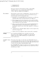
Страница 79: ... or press a key to try to wake up the PC If you cannot wake up the PC and you still cannot turn it off using the power button unplug the PC from the power supply PC does not make a buzzing or beeping sound when you press the power button but you are still unable to turn it off That you have saved all data and exited all programs Savealldataandexitallprograms if you can Press the power button and k...

Страница 80: ...l replace the old password which you had forgotten Press F3 to save the new Password and exit Setup You have forgotten the Administrator password Switch off the PC and remove the power cord Remove the computer s cover Set switch 6 on the system board switch block to ON Switch on the PC and allow it to complete its startup routine A message is displayed Switch off the computer Reset switch 6 to OFF...

Страница 81: ...ected to the system board and to the LAN board Refer to page 20 if you have a desktop model or page 46 if you have a minitower model for more information Refer to the LAN board documentation for instructions about installing and using the LAN board Check that the Wake On LAN field is set to enabled in the Setup program s Advanced Power Management Setup menu You need to restart the PC and press the...

Страница 82: ... available for the sound board Check that you have followed the installation instructions provided with the sound board If there is still a problem Restart the PC and press F2 when F2 Setup is displayed Reserve an IRQ for the ISA sound board You can reserve IRQ 5 IRQ 9 IRQ 10 or IRQ 11 for this purpose To do this go to the Plug and Play Setup submenu of the Advanced menu and then set the chosen IR...

Страница 83: ...o low or no audio at all Check that the microphone specifications meet the requirements of the 16 bit sound components The microphone should be a 600 ohm electret type Humming noise If the power grounding of your audio components is inadequate a humming noise may be generated Plug all devices into adjacent power outlets outlets within 5 cm 2 inches of each other or use line filters Occasional crac...

Страница 84: ...e documentation and or the operating system documentation for guidance Date and time are wrong The date and time can be incorrect for the following reasons The time has changed to or from Summer Time The PC has been unplugged from the power too long and the battery is discharged To change the date and time use your operating system utilities or the Setup program spid bk spid up4 fb4 Page 74 Tuesda...

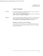
Страница 85: ...that has been installed on the PC after it was manufactured and any personal data that has been generated by applications installed on the PC are not covered by the recovery process Changing the Hard Disk If the hard disk is corrupted and you can no longer use it you should replace it with a new hard disk drive Refer to the information given in earlier chapters of this guide for information about ...

Страница 86: ... disk drive This second hard disk drive must contain the same disk image ie the same operating system drivers and other preloaded software as the original hard disk drive which you need to replace Copying Software from One Hard Disk to Another 1 Connect a bootable hard disk drive from another Windows NT model to a spare IDE connector for example the Slave IDE connector on the Primary IDE cable ass...

Страница 87: ...tains the master versions of the HP software NOTE You should be able to download any drivers etc that you need from the HP Web site http www hp com go vectrasupport After downloading you can create an IDE and VIDEO directory in the MASTERS directory and copy the installation files to the respective directories Follow the instructions in the readme files supplied with the IDE and the VIDEO drivers ...

Страница 88: ...rking skip the network installation during setup by selecting the option Do not connect this computer to a network at this time 4 Confirm the VGA compatible display adapter as video adapter at the end of the setup process 5 After the reboot you will have a basic version of NT 4 0 installed OPTIONAL If you install from CD ROM then you should copy the i386 directory from the CD ROM to your HDD it is...

Страница 89: ...e and run the installation program HP DiagTools Download the HP DiagTools installation software from the HP Web site http www hp com go vectrasupport Refer to page 82 for more information about installing and using HP DiagTools Installation of Customer Specific Software As the hard disk is now restored to its original HP preloaded format you can now proceed with customer specific software Don t fo...

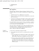
Страница 90: ...oppy disk CAUTION You should not use the BootBlock procedure as the normal method of updating the BIOS Use it only as a recovery process BootBlock is loaded during manufacturing and should never be updated Using the BootBlock feature To recover from a faulty BIOS you need to use a floppy disk containing the BIOS file HS0x0x ROM but renamed to AMIBOOT ROM you need to rename the file yourself To act...

Страница 91: ...minutes When the flashing is complete the PC reboots automatically 7 Shut down the PC and disconnect the PC s power cord 8 Remove the cover and set switches 5 and 6 back to the Off position 9 Replace the cover reconnect all power cords and cables remove the floppy disk from the floppy disk drive and switch on the PC The PC should boot normally CTRL HOME spid bk spid up4 fb4 Page 81 Tuesday May 12 ...

Страница 92: ...support The latest version of this utility can be obtained from HP Electronic Information Services available 24 hours per day 7 days per week To access these services you should connect to the HP Web site at http www hp com go vectrasupport Starting The Diagnostics Utility To start the Vectra Hardware Diagnostics utility 1 Quit all applications shut down the operating system and restart your PC a ...

Страница 93: ...h testing of your system s individual components you will need to carry out the Advanced System Tests NOTE The advanced test phase of this utility is suitable for intermediate and advanced users only Support Ticket To produce a complete record of your system s configuration and test results you will need to create a Support Ticket This can then be sent via e mail or fax to your local or HP dedicat...

Страница 94: ...t the PC will boot on that hard disk drive NOTE The first time you start your PC the PC will by default boot from the hard disk drive connected to the Master IDE connector on the Primary IDE cable IDE 0 The drive positions on the two IDE cables are When booting from a different hard disk drive make sure you know its physical position on the cable Cable Connector BIOS ID in Setup Program Primary ID...

Страница 95: ...ff normal default On clear CMOS and reload default values in Setup 6 Password Off enabled default On disabled clear User and Administrator passwords Processor Frequency Switch 1 Switch 2 Switch 3 Switch 4 233 Off Off On On 266 On On Off On 300 Off On Off On 333 On Off Off On System Board Switches On Off Switch 1 spid bk spid up4 fb4 Page 85 Tuesday May 12 1998 1 11 PM ...

Страница 96: ...t of 25 W between all supply rails NOTE There is a maximum of 95 W available for all accessory slots Acoustic Noise Emission Power Consumption Windows NT 115 V 60 Hz 230 V 50 Hz Operating with input output 34 1 W 35 W Operating without input output 34 W 34 8 W Standby 23 W 23 4 W Off 2 36 W 2 37 W V standby power 720 mA 5 V 3A limit per slot limited by system board 12 V 0 8A limit per slot limited...

Страница 97: ...V ac 200 240 V ac all models have voltage selection switch Input frequency 45 66 Hz Maximum output power 145 W continuous Characteristic Description Weight excluding display and keyboard 9 8 kg 21 56 pounds Dimensions Width 19 cm 7 48 inches Height 40 cm 15 75 inches Depth 45 2 cm 17 80 inches Footprint 0 0817 m2 0 879 ft2 Storage temperature 20 ºC to 60º 4 ºF to 140 ºF Storage humidity 8 to 80 re...

Страница 98: ...RQ2 Cascade IRQ3 NS309 COM2 COM4 IRQ4 NS309 COM1 COM3 IRQ5 Free IRQ6 NS309 flexible disk drive controller IRQ7 NS309 LPT IRQ8 PIIX4e RTC IRQ9 Free if not used by video card IRQ10 Free if not used by onboard USB controller IRQ11 NS309 keyboard controller IRQ12 NS309 mouse IRQ14 PIIX4e IDE channel 1 IRQ15 PIIX4e IDE channel 2 DMAs used by PC DMA 0 free DMA 1 free DMA 2 NS309 flexible disk drive cont...

Страница 99: ...reset and Fast A20 00A0 00A1 Slave interrupt controller 00C0 00DF DMA controller 2 00F0 00FF Co processor error 0170 0177 IDE secondary channel 01F0 01F7 IDE primary channel 0278 027F LPT 2 02E8 02EF Serial port 4 COM4 02F8 02FF Serial port 2 COM2 0372 0377 IDE secondary channel secondary flexible disk drive 0378 037A LPT1 03B0 03DF VGA 03E8 03EF COM3 03F0h 03F5 Flexible disk drive controller 03F6...

Страница 100: ... provide a comprehensive range of service and support options To learn more about these service and support options please connect to the HP Web site at http www hp com go vectra or go directly to support at http www hp com go vectrasupport HP s Web site has a vast range of information about HP products services and support including Description of HP s services and support options Support documen...

Страница 101: ...l port POST error 66 passwords administrator 55 BIOS using 54 forgotten 70 setting 54 user 56 PC cannot turn off 69 no power 59 nothing displayed on the screen 60 physical characteristics 87 power consumption 86 power supply unit removing 31 replacing 31 problems audio 73 beep code 68 BIOS update failure 80 cannot turn PC off 69 CD ROM drive 64 CMOS 65 floppy disk drive 63 hard disk contents lost ...

Страница 102: ...Part Number Created in D6538 UPG ABA France 05 98 spid bk spiddtbc fb4 Page 94 Tuesday May 12 1998 1 11 PM ...

Отзывы: