In
stal
lin
g the
Sw
it
ch
Installing the Switch
Installation Procedures
RPS/EPS Operation
The RPS/EPS monitors the power signal from the switch by detecting that the
RPS/EPS is connected to a switch with an RPS/EPS cable. When the power
from the switch is no longer detected, the RPS/EPS will turn on and provide
power to the switch within 1 millisecond.
The RPS/EPS supports hot plugging of the RPS/EPS cable without causing a
reboot of the switch or causing the power supply in either the RPS/EPS or
switch to shut down temporarily or permanently. For more information refer
to the documentation that came with the RPS/EPS.
Operating Characteristics of the 600 RPS/EPS (J8168A)
The 600 RPS/EPS has six RPS ports, each of which can provide redundant
+12V power to a connected switch, but only one connector can provide this
power at a given time.
If a switch with no AC power is connected to an operating 600 RPS/EPS, it
will receive power if power is available (no higher priority port is already using
the RPS power).
If two or more devices fail, priority goes to the device plugged into the lower
numbered port on the 600 RPS/EPS unit. Consequently the most important
switch should be plugged into port one on the 600 RPSEPS. In this state, the
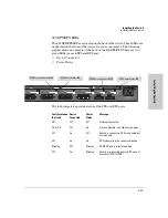
“Connected” LED should be ON, and the “Power Status” LED should be
BLINKING on the lower priority RPS port not supplying power. (Refer to the
documentation that came with your 600 RPS/EPS unit.)
The 600 RPS/EPS also has two EPS Ports. The 600 RPS/EPS can provide a
maximum of 408 watts of PoE power to a switch. It is important to understand
the PoE power requirements of the 2600-PWR Series switches because if the
PoE power is not planned and implemented correctly the end devices
connected to the switch ports may not receive power if an internal switch PoE
power supply should fail. For further information regarding the 600 RPS/EPS
PoE capabilities, see the
PoE Planning and Implementation Guide
and the
ProCurve 600/610 External Power Supplies Installation and Getting Started
Guide
, which is on the Documentation CD-ROM that came with your switch.
For redundant AC power, connect the 600 RPS/EPS to the switch using one
of the six supplied RPS cables. RPS cables are 1.25 meters (4.10 feet) in length.
For redundant or additional PoE power, connect the 600 RPS/EPS to the
switch using one of the two supplied EPS cables. EPS cables are 2.00 meters
(6.56 feet) in length.
2-22
Содержание ProCurve Series 2600
Страница 2: ......
Страница 3: ...ProCurve Series 2600 Switches Installation and Getting Started Guide ...
Страница 60: ... This page is intentionally unused ...
Страница 82: ... This page is intentionally unused ...
Страница 92: ... This page is intentionally unused ...
Страница 101: ...Safety and EMC Regulatory Statements EMC Regulatory Statements Korea Taiwan C 9 Safety and EMC Regulatory Statements ...
Страница 108: ... This page is intentionally unused ...
Страница 115: ......


