background image


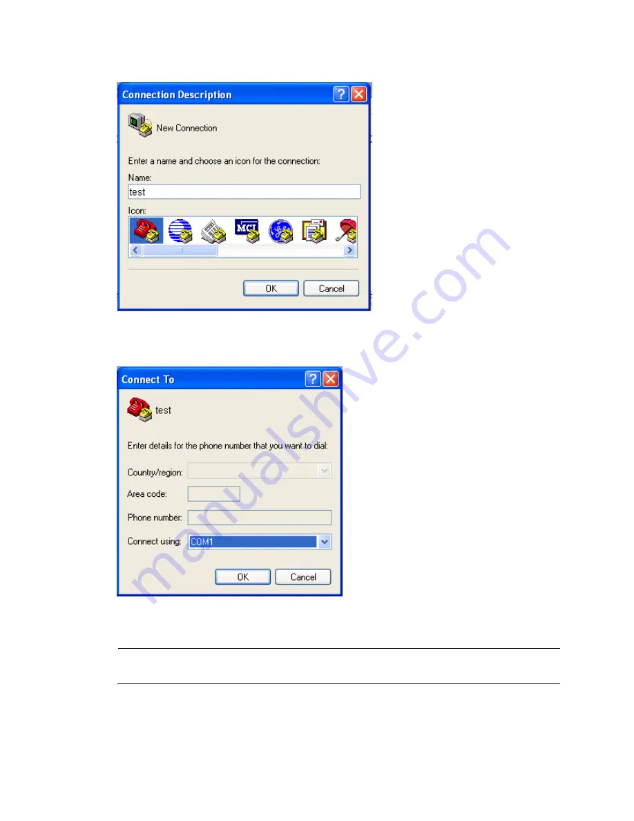
Figure 41


The Connection Description interface of HyperTerminal 


2.


Select the serial port to be used from the 

Connect using

 list, and click 

OK

Figure 42


Select a port for the HyperTerminal connection 


3.


Set 

Bits per second

 to 

9600

Data bits

 to 

8

Parity

 to 

None

Stop bits

 to 

1

, and 

Flow control

 to 

None

and click 

OK


NOTE: 

To restore the default settings, click 

Restore


Defaults


27 

Содержание MSR20-10

Страница 1: ...HP MSR20 1X Router Series Installation Guide Part number 5998 1410 Document version 6PW101 20140523 ...

Страница 2: ...MATERIAL INCLUDING BUT NOT LIMITED TO THE IMPLIED WARRANTIES OF MERCHANTABILITY AND FITNESS FOR A PARTICULAR PURPOSE Hewlett Packard shall not be liable for errors contained herein or for incidental or consequential damages in connection with the furnishing performance or use of this material The only warranties for HP products and services are set forth in the express warranty statements accompan...

Страница 3: ...12 Installing the router 14 Check before installation 14 Installation flow 14 Installing the router 15 Installing the router to a workbench 15 Installing the router on a wall 16 Installing the router to a 19 inch rack 17 Grounding the router 18 Installing an antenna 20 Installing interface modules 21 Connecting interface cables 22 Connecting the console cable and setting terminal parameters 26 Con...

Страница 4: ...word loss 38 Interface module cable and connection failure 38 Appendix A Technical specifications 40 MSR20 1X specifications 40 Antenna specifications 41 Appendix B LEDs and Reset button 42 LEDs 42 MSR20 10 42 MSR20 11 42 MSR20 12 43 MSR20 12 W 44 MSR20 12 T 45 MSR20 12 T W NA 45 MSR20 13 46 MSR20 13 W MSR20 13 W NA 47 Reset button 48 Appendix C Setting the fixed E1 port impedance 49 Appendix D Ar...

Страница 5: ...A MSR20 12 T W NA JF240A MSR20 13 JF808A MSR20 13 W JG210A MSR20 13 W NA This chapter describes the chassis panel views of these routers NOTE The chassis panel views in this document are for illustration only and might slightly differ from the actual panel views MSR20 10 panel views Figure 1 MSR20 10 front panel 1 Power switch 2 Power receptacle 3 USB port 4 Reset button 1 ...

Страница 6: ...hernet WAN port ETH0 MSR20 11 panel views Figure 3 MSR20 11 front panel 1 Power switch 2 Power receptacle 3 USB port 4 Reset button Figure 4 MSR20 11 rear panel 1 Grounding screw 2 Console AUX port 3 Synchronous asynchronous serial port Serial 0 4 SIC DSIC slot 5 Ethernet LAN ports ETH1 to ETH4 6 Ethernet WAN port ETH0 2 ...

Страница 7: ...port 4 Reset button Figure 6 MSR20 12 rear panel 1 Grounding screw 2 Console AUX port 3 E1 port EPRI0 4 SIC DSIC slot 5 Ethernet LAN ports ETH1 to ETH4 6 Ethernet WAN port ETH0 MSR20 12 W panel views Figure 7 MSR20 12 W front panel 1 Power switch 2 Power receptacle 3 USB port 4 Reset button 3 ...

Страница 8: ...et LAN ports ETH1 to ETH4 8 Ethernet WAN port ETH0 MSR20 12 T panel views Figure 9 MSR20 12 T front panel 1 Power switch 2 Power receptacle 3 USB port 4 Reset button Figure 10 MSR20 12 T rear panel 1 2 3 4 5 6 1 Grounding screw 2 Console AUX port 3 T1 port TPRI0 4 SIC DSIC slot 5 Ethernet LAN ports ETH1 to ETH4 6 Ethernet WAN port ETH0 4 ...

Страница 9: ...et button Figure 12 MSR20 12 T W NA rear panel 1 Grounding screw 2 Antenna port 3 Console AUX port 4 T1 port TPRI0 5 SIC DSIC slot 6 Antenna port 7 Ethernet LAN ports ETH1 to ETH4 8 Ethernet WAN port ETH0 MSR20 13 panel views Figure 13 MSR20 13 front panel 1 Power switch 2 Power receptacle 3 USB port 4 Reset button 5 ...

Страница 10: ...N port ETH0 7 ISDN BRI S T0 port MSR20 13 W panel views Figure 15 MSR20 13 W front panel 1 Power switch 2 Power receptacle 3 USB port 4 Reset button Figure 16 MSR20 13 W rear panel 1 Grounding screw 2 Antenna port 3 Console AUX port 4 G SHDSL0 port 5 SIC DSIC slot 6 Antenna port 7 Ethernet LAN ports ETH1 to ETH4 8 Ethernet WAN port ETH0 9 ISDN BRI S T0 port 6 ...

Страница 11: ...wer switch 2 Power receptacle 3 USB port 4 Reset button Figure 18 MSR20 13 W rear panel 1 Grounding screw 2 Antenna port 3 Console AUX port 4 G SHDSL0 port 5 SIC DSIC slot 6 Antenna port 7 Ethernet LAN ports ETH1 to ETH4 8 Ethernet WAN port ETH0 9 ISDN BRI S T0 port 7 ...

Страница 12: ...oving the chassis Safety with electricity Locate the emergency power off switch in the room before installation Shut the power off at once in case accident occurs Make sure that the router has been correctly grounded Do not open or close the chassis cover when the router is powered on Connect the interface cables for the router correctly Use an uninterrupted power supply UPS If there are two power...

Страница 13: ...elative humidity 0 C to 40 C 32 F to 104 F 5 to 90 Cleanness Dust buildup on the chassis may result in electrostatic adsorption which causes poor contact of metal components and contact points especially when indoor relative humidity is low In the worst case electrostatic adsorption can cause communication failure Table 2 Dust concentration limit in the equipment room Substance Concentration limit...

Страница 14: ...ventive wrist strap 2 Lock 3 Alligator clip CAUTION Check the resistance of the ESD preventive wrist strap for safety The resistance reading should be in the range of 1 to 10 megohm Mohm between human body and the ground No ESD preventive wrist strap is provided with the HP MSR20 1X router Prepare it yourself EMI All electromagnetic interference EMI sources from outside or inside of the router and...

Страница 15: ...ack has a good ventilation system The rack is sturdy enough to support the router and installation accessories Make sure that the size of the rack is appropriate for the router and that there is enough clearance around the left and right sides of the router for heat dissipation For heat dissipation and device maintenance make sure the front and rear of the rack should be at least 0 8 m 2 62 ft awa...

Страница 16: ...he router far away from radio stations radar and high frequency devices working in high current Use electromagnetic shielding when necessary Lightning protection The grounding cable of the chassis is well grounded The grounding terminal of the AC power receptacle is well grounded A port lightning arrester is installed Optional A power lightning arrester is installed Optional A signal lightning arr...

Страница 17: ... router is far away from any moist area and heat source The emergency power switch in the equipment room is located Tools Installation accessories supplied with the router User supplied tools Reference Documents shipped with the router Online documents ...

Страница 18: ...hen maintaining the router Therefore before you open the chassis cover please contact your local sales agent to ask for permission or follow the instruction as provided by the agent otherwise the user takes full responsibility for own operation if any maintenance failure occurs Check before installation You have read through the chapter Preparing for installation carefully All requirements in the ...

Страница 19: ...nd Install the router to a rack Install the router to a workbench Yes No Install wall mounting screws Install the router to a wall Connect the router to a console terminal Connect the power cord Installing the router Installing the router to a workbench You can install the MSR20 1X router to a clean workbench When installing the router follow these guidelines Make sure that the workbench is stable...

Страница 20: ...er on a wall To install the router to a wall 1 Mark the locations of the two mounting holes on the wall 2 Drill two holes in the wall Drill each hole at least 22 mm 0 87 in deep and make sure the two holes are on the same horizontal line and 170 mm 6 69 in apart 3 Insert an anchor into each hole until it is all flush with the wall surface 4 Drive the screws into the anchors keeping the screws at l...

Страница 21: ... the network interface facing downwards and the two sides with ventilation holes vertical to the ground Installing the router to a 19 inch rack NOTE The MSR20 1X router does not provide mounting brackets To install the router to a rack order mounting brackets 17 ...

Страница 22: ...n requirements and rustproof treatment has been made to their surfaces Figure 23 MSR20 1X mounting brackets 1 Left front mounting bracket 2 Right front mounting bracket Figure 24 Fix the router to the rack 3 4 2 1 WARNING Mounting brackets support only the weight of the router To avoid damage to the router do not place any objects on the router Grounding the router WARNING Correctly connecting the...

Страница 23: ...assis 2 Put the supplied OT terminal of the grounding cable on the grounding screw 3 Fasten the grounding screw which is attached with the OT terminal of the grounding cable into the grounding screw hole with a screwdriver 4 Attach the other end of the grounding cable to the grounding strip or grounding hole in the chassis Figure 25 Protection grounding terminal of the router 1 Grounding screw 2 O...

Страница 24: ... ft or longer angle iron or steel tube into the earth ground to serve as a grounding conductor Figure 28 Ground the switch by burying the grounding conductor into the earth ground 1 Earth 2 Joint 3 Angle iron Installing an antenna To install an antenna 1 Adjust the angle of the antenna to 180º 2 Fasten the antenna onto the router Avoid over tightening The antenna must be vertical to the ground or ...

Страница 25: ...d off If not power off the router To install a SIC interface module 1 Remove the screws of the filler panel by using a Phillips screwdriver and then remove the filler panel 2 Push the SIC interface module into the SIC slot along the slide rails until it closely mates with the rear panel of the router 3 Use a flat blade screwdriver to fasten the captive screws to fix the SIC interface module to the...

Страница 26: ...ix the DSIC interface module to the router Figure 31 Install a DSIC interface module 1 2 3 4 5 Connecting interface cables Before powering on the router connect the interface cables of the router Connecting an Ethernet cable To connect a copper Ethernet port connect one end of the Ethernet cable to an Ethernet port on the router and the other end to the peer device For a 10 100 Mbps copper Etherne...

Страница 27: ...etwork end V 35 DCE cable 34PIN female connector at the network end X 21 DTE cable DB 15 male connector at the network end X 21 DCE cable DB 15 female connector at the network end RS449 DTE cable DB 37 male connector at the network end RS449 DCE cable DB 37 female connector at the network end RS530 DTE cable DB 25 male connector at the network end RS530 DCE cable DB 25 female connector at the netw...

Страница 28: ...other end of the coaxial connectors to the remote network equipment through 75 ohm E1 trunk cables if cable extension is needed CAUTION Connect the wire marked TX in the E1 cable to the peer wire marked RX and the wire marked RX to the peer wire marked TX Figure 35 Connect an E1 interface cable Figure 36 Extending an E1 75 ohm unbalanced coaxial cable Router Network devices such as DDN DB 15 Coaxi...

Страница 29: ...terface and the other end to the S T interface on NT1 2 If the line is an ISDN S T interface line connect one end of the Ethernet cable to the ISDN BRI S T interface and the other end with the ISDN S T interface line Figure 38 Connect an ISDN BRI S T interface cable Connecting a G SHDSL interface cable An MSR20 13 G SHDSL interface cable is a telephone cable with ferrite core one RJ 45 connector t...

Страница 30: ...to the console port of the router Figure 40 Connect the console cable 1 Console cable 2 Console port CONSOLE CAUTION When connecting the PC to the router by using a console cable connect the DB 9 end of the console cable to the serial port of the PC first and then connect the RJ 45 connector of the console cable to the console port of the router Setting console terminal parameters To set console t...

Страница 31: ...rt to be used from the Connect using list and click OK Figure 42 Select a port for the HyperTerminal connection 3 Set Bits per second to 9600 Data bits to 8 Parity to None Stop bits to 1 and Flow control to None and click OK NOTE To restore the default settings click Restore Defaults 27 ...

Страница 32: ...al port parameters 4 Select File Properties in the HyperTerminal window Figure 44 HyperTerminal window 5 Click the Settings tab set the emulation to VT100 or Auto Detect and click OK in the Test Properties dialog box 28 ...

Страница 33: ...ed with the router to the power socket on the rear panel and the other end to an AC power source Figure 46 Connect the AC power cord Verifying the installation After installation verify the following items before powering on the router Enough space is reserved around the router for heat dissipation and the router is sturdy Antennae USB devices and interface modules are correctly installed The rout...

Страница 34: ...rce Turn on the power switch on the router WARNING Before powering on the router locate the power switch of the power source so that you can disconnect the power supply in time in case of an emergency Startup process After power on the router initializes its memory and then runs the extended BootWare The following information appears on the terminal screen System is starting Do you want to check S...

Страница 35: ...after the router is powered on Table 5 Normal LED status after the router is powered on LED Status Meaning PWR Steady green The power supply is working properly SYS Flashing green slowly The system is working properly 2 The configuration terminal displays information correctly You can see the startup window on the local configuration terminal For more information see Startup process 3 After the po...

Страница 36: ...esponsibility for own operation if any maintenance failure occurs Locating the internal modules in the router Opening and removing the chassis cover WARNING To avoid bodily injuries and device damages make sure that all power sources to the router are disconnected before maintaining any hardware modules of the router When maintaining the router hardware always wear an ESD preventive wrist strap an...

Страница 37: ...Figure 47 Remove the chassis cover Locating the internal modules in the router Figure 48 Internal architecture of an MSR 20 1x router 1 VPM module 2 Built in WLAN module 3 Front panel 33 ...

Страница 38: ... install a VPM module 1 Align the golden finger of the VPM module with the VPM module slot on the motherboard of the router Insert the VPM module into the slot at a 45 degree angle 2 Tilt the VPM module up to the vertical position until you hear a click This click indicates the VPM module is firmly inserted in the slot Figure 50 Install a VPM module Removing a VPM module To remove a VPM module 1 P...

Страница 39: ...35 Figure 51 Remove a VPM module ...

Страница 40: ...nt panel is off it indicates that the power supply is faulty To troubleshoot the power supply failure 1 Power off the router 2 Check whether the power cords of the router are firmly connected 3 Check whether the power source is operating properly 4 Check whether the power cord is damaged If the cause cannot be located in the steps above and the problem persists contact your local sales agent Confi...

Страница 41: ...ssword loss 1 Enter the main BootWare menu and select 6 to boot the system by ignoring the system configuration The system prompts the following Flag Set Success The output shows that the setting succeeded 2 When the main BootWare menu appears again and select 0 to reboot the system System is rebooting now System start booting Booting Normal Extend BootWare 3 Set a new password in system view afte...

Страница 42: ...nables you to switch between four super levels In the case of super password loss you cannot perform higher level operations You can clear the super password by selecting 8 on the main BootWare menu EXTEND BOOTWARE MENU 1 Boot System 2 Enter Serial SubMenu 3 Enter Ethernet SubMenu 4 File Control 5 Modify BootWare Password 6 Skip Current System Configuration 7 BootWare Operation Menu 8 Clear Super ...

Страница 43: ...whether the router supports the interface module 2 Check whether the interface module is installed in the correct slot 3 Check whether the interface cable is correctly selected 4 Check whether the interface cable is correctly connected ...

Страница 44: ...A T1 port N A N A N A N A 1 1 N A N A N A G SHDSL BIS 4 wire port N A N A N A N A N A N A 1 1 1 ISDN BRI S T port N A N A N A N A N A N A 1 1 1 SIC DSIC slot 1 SIC or 1 DSIC Built in WLAN module N A N A N A 802 1 1b g N A 802 11b g NA N A 802 11 b g 802 11b g NA VPM module slot 1 1 1 1 1 1 N A N A N A Memory 256 MB DDR SDRAM Flash 32 MB Dimensions H W D excluding rubber feet and mounting brackets ...

Страница 45: ...rboard By default the impedance of the E1 port on MSR20 12 20 12 W is 75 ohms By using the internal DIP switches you can change the interface impedance to 120 ohms For more information see the chapter Appendix C Setting the fixed E1 port impedance Antenna specifications Table 7 Antenna specifications Item Specification Frequency range 2400 MHz to 2500 MHz Voltage Standing Wave Ratio VSWR 2 0 Input...

Страница 46: ...ing yellow A problem has occurred to the system Off The system has failed to operate properly ETH Front panel Solid green A link is present Flashing green Data is being transmitted or received on the port Off No link is present WLAN Front panel Off No built in WLAN module is provided with the model MSR20 11 Table 9 MSR20 11 LED description LED Location Status Description PWR Front panel Solid gree...

Страница 47: ...data is being transmitted or received MSR20 12 Table 10 MSR20 12 LED description LED Location Status Description PWR Front panel Solid green The power supply is connected Off The power supply is not connected SYS Front panel Fast flashing green The system is starting up Slow flashing green The system is operating properly Fast flashing yellow A problem has occurred to the system Off The system has...

Страница 48: ...ast flashing yellow A problem has occurred to the system Off The system has failed to operate properly ETH Front panel Solid green A link is present Flashing green The port is transmitting or receiving data Off No link is present WLAN Front panel Slow flashing green The system is operating properly Fast flashing green The device is working under a large amount of traffic Off The system is operatin...

Страница 49: ... green The port is transmitting or receiving data Off No link is present WLAN Front panel Off No built in WLAN module is provided with the model LINK ACT Rear panel Solid green A TPRI0 link is present Flashing green Data is being transmitted or received Off No carrier signal is received LP AL Rear panel Solid green The TPRI0 port is in loopback state Flashing green One of the following alarms is g...

Страница 50: ...em is operating abnormally LINK ACT Rear panel Solid green A TPRI0 link is present Flashing green Data is being transmitted or received Off No carrier signal is received LP AL Rear panel Solid green The TPRI0 port is in loopback state Flashing green One of the following alarms is generated AIS LFA or RAI Off No loopback or alarm has occurred MSR20 13 Table 14 MSR20 13 LED description LED Location ...

Страница 51: ...is being transmitted or received in the B2 channel LINK ACT Rear panel Solid green A G SHDSL BIS link is present Flashing green Data is being transmitted or received Off No carrier signal is received MSR20 13 W MSR20 13 W NA Table 15 MSR20 13 W MSR20 13 W NA LED description LED Location Status Description PWR Front panel Solid green The power supply is connected Off The power supply is not connect...

Страница 52: ...ransmitted or received in the B1 channel B2 Front panel Solid green Data is being transmitted or received in the B2 channel Off No data is being transmitted or received in the B2 channel LINK ACT Rear panel Solid green A G SHDSL BIS link is present Flashing green Data is being transmitted or received Off No carrier signal is received Reset button The MSR20 1X has a Reset button to restart the syst...

Страница 53: ...R20 12 20 12 W is 75 ohms By using the internal DIP switches you can change the interface impedance from 75 ohms to 120 ohms Figure 52 Default setting of DIP switches on 1 2 3 4 5 6 7 8 Table 1 DIP switch setting description DIP Description Configuration of 75 ohm impedance Configuration of 120 ohm impedance 1BIT 75 ohm 120 ohm selection switch ON OFF 2BIT ON OFF 3BIT ON OFF 4BIT ON OFF 5BIT ON OF...

Страница 54: ... grounding mode selection switch N A OFF RxShield is grounded via capacitance ON RxShield is grounded directly NOTE HP recommends that you select the DIP switch of the fixed E1 port in this way when you connect 75 ohm cable flip BIT1 8 to ON when you connect 120 ohm cable flip BIT1 8 to OFF By default all of the DIP switches are factory configured to ON In other words the impedance of E1 port is 7...

Страница 55: ...asynchronous or Ethernet port X Number of the slot where an interface module resides Y Sequence number of an interface on an interface module Interfaces on the same interface module have the same slot number X and are numbered from 0 in ascending order from left to right when you face the interface module For example the fixed WAN port on the MSR20 1X is nubmered Ethernet 0 0 the four fixed Ethern...

Страница 56: ...system 9 E EMI 10 ESD prevention 10 Examining the installation site 8 G Garbled terminal display 37 General safety recommendations 8 Grounding the router 18 I Installation flow 14 Installation tools 1 1 Installing a VPM module 34 Installing an antenna 20 Installing and removing a VPM module 34 Installing interface modules 21 Installing the router 15 Installing the router on a wall 16 Installing th...

Страница 57: ...tions 8 Safety symbols 8 Safety with electricity 8 Slot arrangement 1 Starting up and configuring the router 30 Super password loss 38 T Temperature and humidity 9 U User password loss 37 V Verifying the installation 29 2 ...

Отзывы: