26
Installing the enclosures
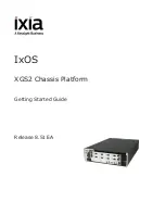
Figure 14
Fault-tolerant cabling connections showing maximum number of enclosures of same type
The figure above provides sample diagrams reflecting fault-tolerant cabling of a maximum number of
supported MSA 2040 enclosures. The diagram at left shows fault-tolerant cabling of an MSA 2040
controller enclosure and seven LFF drive enclosures; whereas the diagram at right shows fault-tolerant
cabling of an MSA 2040 controller enclosure and seven D2700 drive enclosures.
P1
Controller A
Controller B
1A
1B
P2
P1
P1
P1
P1
P1
2A
2B
3A
3B
4A
4B
P2
P2
P2
P2
P2
= LFF 12-drive enclosure
1
= SFF 25-drive enclosure
2
Drive enclosure IOM face plate key:
Controller A
Controller B
In
Out
In
Out
In
Out
In
Out
In
Out
1A
1B
2A
2B
3A
3B
4A
4B
8A
8B
In
Out
In
Out
5A
5B
In
Out
In
Out
6A
6B
In
Out
In
Out
7A
7B
In
Out
In
Out
Note:
The maximum number of supported drive
enclosures (7) may require purchase of
additional longer cables.
2
2
2
1
1
1
1
1
1
1
P2
P1
P2
P1
8A
8B
P1
P1
5A
5B
P2
P2
2
P1
P1
6A
6B
P2
P2
2
P1
P1
7A
7B
P2
P2
2
2
In
Out
Содержание MSA 2040
Страница 8: ...8 Figures ...
Страница 10: ...10 Tables ...
Страница 32: ...32 Installing the enclosures ...
Страница 44: ...44 Connecting hosts ...
Страница 50: ...50 Connecting to the controller CLI port ...
Страница 52: ...52 Basic operation ...
Страница 70: ...70 Troubleshooting ...
Страница 74: ...74 Support and other resources ...
Страница 76: ...76 Documentation feedback ...
Страница 88: ...88 LED descriptions ...
Страница 94: ...94 Electrostatic discharge ...
Страница 100: ...100 Index ...