


B-34
5.
Be sure you have already checked the SCSI ID of the drive you
want to install using the method described at the beginning of
this section.
6.
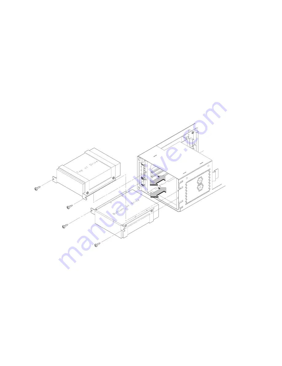
With the disk mounting bracket between the guides on each side
of the Storage Assembly, slide the disk into the Storage Assem-
bly, securing it to the drawer with two side screws. See
Figure B–20. Do not over-tighten the side screws.
The drives should be placed in the drive bays with the bottom of
each drive toward the middle, as shown in Figure B–20. Refer to
Figure B–18 for drive orientation in the bracket.
Figure B–20.Placing Hard Drives in Storage Drawer
Содержание J282
Страница 9: ...viii Glossary Index ...
Страница 13: ...xii ...
Страница 14: ...xiii Preface ...
Страница 28: ...1 9 Removable Device Bays 2 Figure 1 3 System Unit with Removable Device Door Open ...
Страница 50: ...2 8 5 Gently push the disc tray in until it is closed as shown in Figure 2 4 Figure 2 4 Disc Tray Closed ...
Страница 112: ...A 2 ...
Страница 118: ...A 8 ...
Страница 131: ...B 13 Figure B 5 Removing EMI Plate 8 Remove the two M 3 screws from the fan ...
Страница 135: ...B 17 SCSI ID 3 2 default 1 4 5 6 SCSI ID 0 Figure B 8 CD ROM Drive SCSI Address Jumper Settings ...
Страница 142: ...B 24 ÅÅ ÅÅ ÅÅ ÅÅ Top View of Floppy Disk Drive 1 2 3 SCSI Terminators Figure B 13 Floppy Drive Terminators ...
Страница 148: ...B 30 6 5 4 3 2 1 0 15 14 13 12 11 10 9 8 Figure B 17 Typical Hard Drive Jumper Settings ...
Страница 149: ...B 31 PCB Side of Drive Top Drive Bottom Drive Figure B 18 Replacing Hard Drive Mounting Bracket and Drive Orientation ...
Страница 162: ...B 44 Figure B 26 Replacing the CPU Assembly ...
Страница 173: ...B 55 Figure B 35 PCI EISA I O Assembly ...
Страница 179: ...B 61 8 Insert cover in guide and secure with screw Refer to Figure B 41 Figure B 41 Replacing PCI EISA Assembly Cover ...
Страница 183: ...B 65 ...
Страница 210: ...C 27 Figure C 1 Rear Panel SCSI Connectors with Terminators Attached ...
Страница 278: ...Index 6 0 0 0 0 0 0 0 0 0 0 0 0 0 T See also 0 U 0 V W ...