8
NOTE:
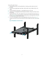
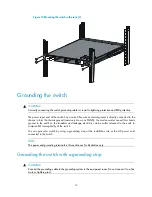
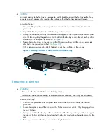
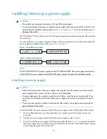
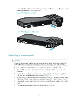
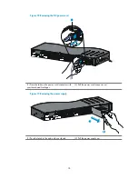
If a rack shelf is available, you can put the switch on the rack shelf, slide the switch to an appropriate
location, and attach the switch to the rack with the mounting brackets.
Attaching the mounting brackets, chassis rails, and grounding
cable to the chassis
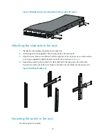
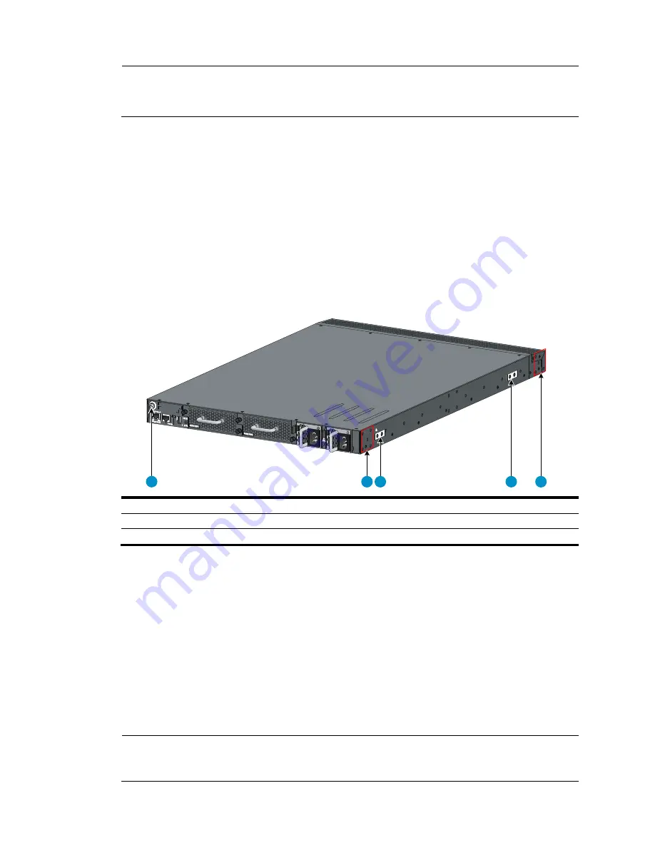
The following mounting positions are available on an HP FlexFabric 5930-/HP FlexFabric
5930- TAA switch:
•
One front mounting position (near the network ports) and one rear mounting position (near the
power supplies) for installing mounting brackets
•
One primary grounding point (with a grounding sign) and two auxiliary grounding points
Figure 5
Identifying the mounting and grounding positions of the HP FlexFabric 5930-/HP
FlexFabric 5930- TAA
(1) Auxiliary grounding point 2
(2) Rear mounting position
(3) Primary grounding point
(4) Auxiliary grounding point 1
(5) Front mounting position
Attaching the mounting brackets and chassis rails to the chassis
1.
Align the mounting brackets with the screw holes in the rear mounting position (see
Figure 6
) or
front mounting position (see
Figure 7
).
2.
Use M4 screws (supplied with the switch) to attach the mounting brackets to the chassis.
3.
Align the chassis rails with the rail mounting holes in the chassis:
{
If the mounting brackets are in the rear mounting position, align the chassis rails with the screw
holes at the front of the side panels (see
Figure 6
).
{
If the mounting brackets are in the front mounting position, align the chassis rails with the screw
holes at the rear of the side panels (see
Figure 7
).
4.
Use M4 screws (supplied with the switch) to attach the chassis rails to the chassis.
NOTE:
Secure the mounting brackets and chassis rails to both sides of the chassis in the same way.
1
2 3
4
5


