background image

18

HP Surestore FC Switch 6164 Installation and Reference Guide

The acceptable environmental ranges for the FC 6164 are shown in 

Table 2

These environmental ranges also apply to each switch.

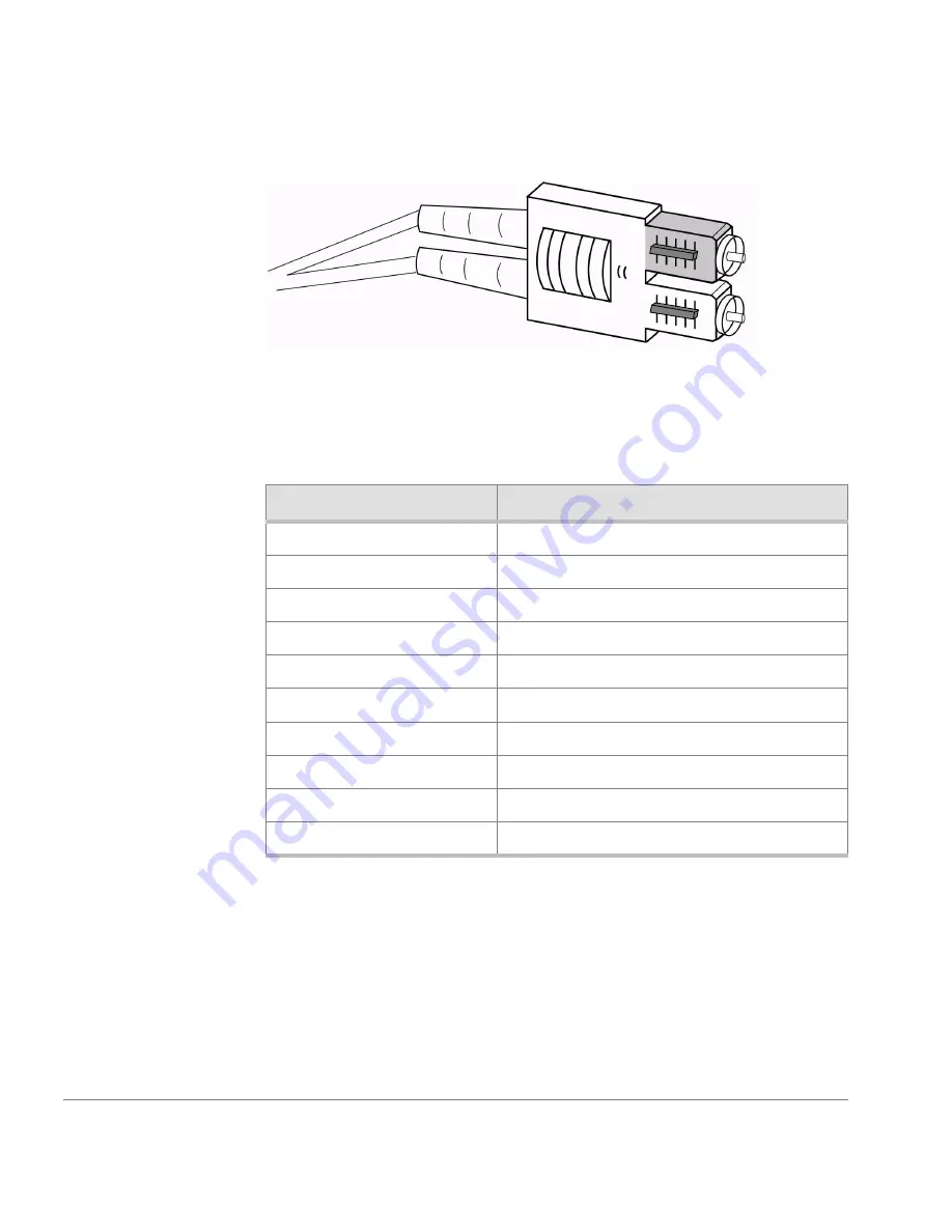
Figure 1. Dual SC Fiber Optic Plug Keyed Connector

Table 2. FC 6164 Environmental Specifications

Specification

Value

Temperature (operating)

10 to 40

°

C

Temperature (nonoperating) -35 to 65

°

C

Operating humidity

5 to 85% noncondensing at 40

°

C

Nonoperating humidity

95% RH nonconducting at 40

°

C

Operating altitude

0 to 3 km above sea level

Nonoperating altitude

0 to 12 km above sea level

Operating shock

4 G, 11-MS duration, half sine

Nonoperating shock

20 G, 11-MS duration, sq.wave

Operating vibration

5 G, 0 to 3 kHz

Nonoperating vibration

10 G, 0 to 5 kHz

Содержание FC Switch Surestore 6164

Страница 1: ...installation and reference guide hp surestore fc switch 6164 www hp com ...

Страница 2: ... Fabric OS Brocade Fabric Watch Brocade QuickLoop Brocade Remote Switch Brocade Web Tools and Brocade Zoning are trademarks or registered trademarks of Brocade Communications Systems Inc in the United States and or in other countries All other brands product or service names are or may be trademarks or service marks of and are used to identify products of services of their respective owners Brocad...

Страница 3: ...Software Updates 11 1 Introducing the FC 6164 13 Management Tools 14 Fabric level Management Tool 14 Switch level Management Tools 14 2 Mechanical Specifications 15 Chassis level Information 15 Weight Specifications 16 Dimensions 16 Thermal Characteristics 16 GBICs 17 Fiber Optic Cables 17 CONTENTS ...

Страница 4: ...Indicators 22 3 Installing and Configuring the FC 6164 25 Installation Considerations and Safety Guidelines 25 Procedures 26 Items Required 27 Unpacking the FC 6164 28 Installing the FC 6164 in the Rack 28 Configuring the FC 6164 51 4 Maintenance Procedures 57 Switch Replacement Procedure 57 Procedure 58 ISL Cable Replacement Procedure 71 Procedure 72 5 Diagnostics 77 Overview 77 Diagnostic Tests ...

Страница 5: ...erties File 100 Uninstalling Fabric Manager 101 8 Using Fabric Manager 103 Fabric View 103 Fabric Events View 110 Fabric Topology View 111 Name Server Table View 114 Zone Administration View 117 Alias Tab 118 Zone Tab 120 QuickLoop Tab 122 Config Tab 124 Fabric Manager Log 126 Switch View for the FC 6164 126 Switch View for Individual Switches 129 Switch Events View 133 Port Information View 135 P...

Страница 6: ...itch Tab Optional Software 171 QuickLoop Admin Tab 172 Config Admin Tab 175 Extended Fabric Tab Optional Software 177 Telnet Interface 179 9 Telnet Commands 183 islTopoCheck 184 islTopoShow 186 sgroupDelete 189 sgroupRename 191 sgroupSet 193 sgroupShow 196 sgroupSupportShow 198 sgroupSwReplace 202 switchStatusPolicySet 204 switchStatusPolicyShow 207 snmpMibCapSet 209 A FC 6164 Worksheet 211 Produc...

Страница 7: ...7 Revision History July 2001 First release ...

Страница 8: ...8 HP Surestore FC Switch 6164 Installation and Reference Guide ...

Страница 9: ...mation about installing and configuring the FC 6164 Chapter 3 Mechanical Specifications Provides the mechanical details of the FC 6164 Chapter 4 Diagnostics Provides information about diagnostic tests and error messages Chapter 5 Maintenance Procedures Provides maintenance procedures for the FC 6164 Chapter 6 Introducing Fabric Manager Provides an overview of Fabric Manager the management software...

Страница 10: ...the screens available through Fabric Manager Chapter 9 Telnet Commands Provides information about the Telnet commands that are specific to administration of the FC 6164 Title Part Number HP Surestore FC Switch 6164 Documentation CD A7326 11011 HP Surestore FC Switch 6164 Installation and Reference Guide A7326 90902 HP Surestore FC Switch 6164 Quick Start Guide A7326 90901 Distributed Fabrics User ...

Страница 11: ... site located at http www hp com Getting Software Updates Firmware and software updates are found on the HP web site at http www hp com New switch firmware can be installed from the following host operating systems UNIX Windows NT Windows 2000 Windows 98 Windows 95 ...

Страница 12: ...12 HP Surestore FC Switch 6164 Installation and Reference Guide ...

Страница 13: ...k mountable solution comprised of a chassis and six fully integrated switch modules with preconfigured inter switch link ISL fiber optic cables and enhanced management software The FC 6164 includes Fabric Manager a management application that provides a centralized view of the integrated switch modules to simplify administration and maintenance Using this preconfigured stand alone fabric as a buil...

Страница 14: ... seamlessly with Web Tools to provide switch level information Fabric Manager is included with the FC 6164 product and is installed on a workstation computer instead of on the switch thereby using less switch resources The workstation computer must be on the same network as the switches being managed Switch level Management Tools The following software is installed on each of the six switches in t...

Страница 15: ...bles all required ISL inter switch link fiber optic cables and ISL GBICs Chassis level Information The FC 6164 chassis includes cable routing holes in the upper lower and side panels for easy cable management A color coded ISL cable diagram is provided on the inside bottom of the chassis for reference when switches or ISL cables are being replaced see Chapter 4 Maintenance Procedures for the cable...

Страница 16: ...ool the units The direction of air flow is from the air inlet side to the service side the front where the ports and ISL cables are of the units The entire FC 6164 is optimized to provide proper cooling for a maximum power rating of 70 Watts per 2250 switch Total system power is 420 Watts The FC 6164 has an operating range in 10 to 40 C at 3 km 9 800 feet Table 1 Weight Specifications Hardware Wei...

Страница 17: ...ts are not included Standard fiber optic cables can be used for the user ports and connections can be made to the GBICs inserted in the user ports using standard dual SC plug connectors as shown in Figure 1 The fiber optic connectors are keyed and must be inserted into the GBIC module connector in proper alignment CAUTION The fiber optic cables are fragile and should not be bent to a radius of les...

Страница 18: ...ntal Specifications Specification Value Temperature operating 10 to 40 C Temperature nonoperating 35 to 65 C Operating humidity 5 to 85 noncondensing at 40 C Nonoperating humidity 95 RH nonconducting at 40 C Operating altitude 0 to 3 km above sea level Nonoperating altitude 0 to 12 km above sea level Operating shock 4 G 11 MS duration half sine Nonoperating shock 20 G 11 MS duration sq wave Operat...

Страница 19: ... other fibre channel switches to build a scalable SAN fabric capable of supporting large numbers of attached storage devices The FC 6164 supports F_Port FL_Port and E_Port connections and a Distributed Name Server DNS There is no On Off switch the switch is powered on or off when the power cable is connected or disconnected Figure 2 2250 Switch AC module 10 100BaseT port GBIC port DB 9 port ...

Страница 20: ...bre Channel ports 16 GBIC ports Fibre Channel port speed 1 0625 Gbps full duplex Modes of operation Fibre Channel Class 2 service and Fibre Channel Class 3 connectionless service Aggregate switch I O bandwidth 16 Gbps full duplex Frame buffers 16 buffers per port at 2112 bytes per frame Port to port latency Less than 2 microseconds with no contention Data transmission range Up to 500 m 1 625 ft fo...

Страница 21: ...capable of functioning worldwide without voltage jumpers or switches The power supply module is autoranging in terms of accommodating input voltages and line frequencies Environmental Specifications for each Switch The acceptable environmental ranges for the 2250 switch are the same as for the entire FC 6164 and are listed under Thermal Characteristics on page 16 Table 5 Power Supply Requirements ...

Страница 22: ...Receiving light or signal carrier but not yet online No action required Slow yellow on for one second off for one second Port is disabled result of diagnostics or port disable command Reset at management station Fast yellow on for 1 4 second off for 1 4 second Error fault with port Reset switch Steady green Port is online but no traffic connected with device over cable No action required Slow gree...

Страница 23: ...tation AC Power LED Status Description Action No light showing No power is being supplied to the switch Check power cord connection to the switch Steady green Receiving power and switch is online No action required Table 6 LED Status Indicators continued LED Time Interval Status Description Action ...

Страница 24: ...24 HP Surestore FC Switch 6164 Installation and Reference Guide ...

Страница 25: ... in this chapter enter help followed by the command name at the Telnet prompt For example to display information about the fabricShow command enter the following help fabricShow Installation Considerations and Safety Guidelines WARNING The FC 6164 weighs approximately 200 pounds Use proper handling and lifting equipment such as a hydraulic lift to reduce the possibility of injury or product damage...

Страница 26: ...hes secured in the chassis and with one switch partially extended out of the chassis Verify the supply circuit line fusing and wire size are adequate according to the electrical rating on the switch nameplate Verify that all equipment installed in the rack has a reliable branch circuit ground connection It is strongly recommended that the EIA Rack be mechanically secured to prevent tipping over in...

Страница 27: ...ksheet Serial cable connected to the workstation long enough to connect to each of the switches in the chassis Workstation that has a terminal emulator application such as HyperTerminal Six unused IP addresses Ethernet connection between the workstation and the FC 6164 such as through a hub 2 Phillips screwdriver T20 Torx screwdriver Genie lift to transport the switch For information on the lift s...

Страница 28: ... Rackmount Safety Guidelines In a rackmount installation follow these safety guidelines When installing a switch in a closed or multi rack assembly make certain the air temperature measured at the front panel does not exceed 40 C during operation Ensure that the airflow available to the switch is at least 300 cfpm Verify the supply circuit line fusing and wire size are adequate Refer to the switch...

Страница 29: ...ntinue supporting it until it is correctly positioned on the rail tray and fastened to the rack Use extreme caution when handling or transporting the switch to prevent injury to personnel damage to the switch and or damage to the rack and other equipment mounted in it Package Contents Figure 3 shows the major items contained in the FC 6164 shipping carton s Table 7 lists the contents of the shippi...

Страница 30: ...it HP P N A7326 70001 which also includes Software CD Documentation CD and Serial cable H Miscellaneous hardware not shown HP P N A7326 87905 Note The hardware in the Standard hardware package unmarked plastic bag is required to install the switch in an HP rack Some of the hardware in the Standard hardware package and the hardware in the Compaq Rittal hardware package is required to install the sw...

Страница 31: ...ack Use this key to help identify the hardware specified in the installation procedure in this chapter Figure 4 Hardware Key M5 Torx screw with captive lock washer 8 32 x 375 inch flat head Phillips screw M5 Tinnerman nut 10 32 Tinnerman nut 1 4 20 x 1 2 inch Phillips screw and washer 10 32 X 5 8 inch pan head Phillips screw Spacers for Compaq Rittal racks 1 4 inch flat washer M5 flat washer ...

Страница 32: ...not make the rack unstable 15 Rack Units RUs are required see Figure 5 CAUTION The switch must be installed with the front end facing the back of the rack When the switch is mounted this way the air flows through the switch in the same direction as it does through the other equipment in the rack see Figure 5 Figure 5 Switch Mounted Back to Front and Low in the Rack Front of rack Back of switch 15 ...

Страница 33: ... the rack for the switch see the WARNING at the beginning of this section and Figure 5 3 Install the rail tray in the rack a Locate the lowest RU of the 15 you chose for mounting the switch this is RU 1 b Attach the rear rail tray brackets to the rear rack uprights at RU 1 For an HP rack use 1 M5 torx screw for each bracket see Figure 6 For a Compaq Rittal rack insert spacers in the upper and lowe...

Страница 34: ...nore the mounting instructions on the label attached to the rail tray some rail trays do not have this label Figure 6 Installing the Rear Rail Tray Brackets Spacer M5 flat washer M5 Screw with attached lock washer Rear Tray bracket M5 flat washer Compaq Rittal rack M5 Screw with attached lock washer HP rack Rear Tray bracket ...

Страница 35: ...rent styles and different sizes Refer to Figure 5 and Figure 7 to identify the correct Tinnerman nut to use with the rack you are installing the switch in d For a Compaq Rittal rack insert spacers in the holes immediately below the Tinnerman nuts you inserted in Step 3c see Figure 7 Figure 7 Installing Tinnerman Nuts and Spacers on the Front Uprights Inner surface of Compaq Rittal rack Spacer Tinn...

Страница 36: ...ts on the rear rail tray brackets and the posts on the rail tray s front mounting flanges must be inserted in the center holes of RU1 f Insert M5 torx screws through the top holes in both of the rail tray mounting flanges The screws pass through the holes in the rack uprights and thread into the Tinnerman nuts you installed on the uprights in Step 3c Tighten the screws Figure 8 Inserting the Rail ...

Страница 37: ...h side of the rail tray see Figure 9 CAUTION The shim plates must be placed on top of both sides of the rail tray to prevent misalignment between the mounting holes in the switch flanges and the holes in the rack uprights Figure 9 Placing the Shim Plates on the Rail Tray ...

Страница 38: ...t bracketsconsistofa stationaryplateand anadjustable plate that are attached to each other with two screws Remove the screws that attach the adjustable plates to the stationary plates Set the screws and the adjustable plates aside for later use see Figure 11 Figure 10 Installing Tinnerman Nuts in RU 5 and RU 12 Figure 11 Separating the Rack Mount Bracket Plates 1 5 12 11 4 Rack uprights 1 5 12 11 ...

Страница 39: ...12 Do not tighten the screws fully at this time Note Some stationary plates have arrows stamped into them and some do not The arrow determines which side of the switch the plate must be mounted on If the stationary plates provided with the switch do not have arrows they can be mounted on either side Note If you have adequate access to the back of the rack to insert the switch from the back skip St...

Страница 40: ...e front end as described in Steps 7 8 and 9 If you have adequate access to insert the switch into the rack from the back you can skip these steps 7 Remove the four 6 32 x inch flat head screws that attach each of the two hinge plates to the left side of the switch at the front end see Figure 13 Set the screws and the hinge plates aside for later use Figure 13 Removing the Hinge Plates from the Swi...

Страница 41: ...ote The latch plate fits through a cutout in the rack mounting flange on the right side of the switch 9 Remove the eight 10 32 Phillips screws that attach each of the rack mounting flanges to the sides of the switch at the front and remove the rack mounting flanges see Figure 14 Set the rack mounting flanges and the screws aside for later use Figure 14 Removing the Latch Plate and the Mounting Fla...

Страница 42: ...t until it is correctly positioned on the rail tray and fastened to the rack Use extreme caution when handling or transporting the switch to prevent injury to personnel damage to the switch and or damage to the rack and other equipment mounted in it a Place the switch on a lift If you are installing the switch from the front of the rack orient the switch so its front end FACES THE FRONT OF THE RAC...

Страница 43: ...8 to re attach the latch plate see Figure 14 Make sure that there is a gap of approximately 3 16 inch between the edges of the latch plate and the edges of the cutout in the rack mounting flange c Orient the hinge plates so that the sides that have the loops face each other see Figure 15 Use the eight 6 32 x inch flat head screws you removed in Step 7 to re attach the hinge plates to the left side...

Страница 44: ...a through the slotted holes in the stationary plate and into the second set of threaded holes in the adjustable plate from the rack mounting flange see Figure 16 Do not tighten the screws at this time d Repeat Steps b and c for the rack mount bracket on the opposite side of the switch e Move the switch forward in the rack as far as it can go The amount of movement is limited by the rack mount brac...

Страница 45: ... insert the screws through the holes in the rack uprights and into the threaded holes in the flanges of the rack mount bracket adjustable plates see Figure 16 Do not tighten the screws at this time 13 From the back of the rack insert four 10 32 x 5 8 inch Phillips pan head screws with captive lock washers through the holes in the rack mount flanges attached to the front end of the switch and into ...

Страница 46: ...at attach the rack mount bracket adjustable plates to rack uprights then fully tighten the screws that attach the adjustable plates to the stationary plates and the screws that attach the stationary plates to the switch chassis see Figure 16 Figure 17 Attaching the Rack Mount Flanges to the Rack ...

Страница 47: ...the folded ends of the bottom panel see Figure 18 Press the side panel firmly against the upright end of the bottom panel to ensure that the adhesive strip on the side panel makes fullcontactwiththeendofthebottompanel Youcanuseascrewdriver handle to increase the pressure you apply when joining the parts c Repeat Step 15b for the other side panel d Remove the paper backing from the adhesive strips ...

Страница 48: ...act with the folded end of the top panel Repeat this step for the other side panel 16 Install the plenum in the rack a Remove the paper backing from the two adhesive strips on the bottom surface of the plenum b Position the plenum against the back of the switch and slide it down until the adhesive strips on the underside of the plenum contact the shim plates that are on top of the rail tray see Fi...

Страница 49: ... of the bezel that grip the rack uprights and hold the bezel in position Eachof the lower alignment posts fitsintothesecond unused hole above the front mounting flange on each side of the rail tray b Press the sides of the bezel against the rack uprights until the bezel snaps into place Snap the bottom end in first and then the top end c Inspect the bezel to ensure that it is installed so that its...

Страница 50: ...oor so that the hinge pins are between the loops on the hinge plates mounted on the switch see Figure 15 and Figure 21 Note When you rotate the door to the closed position the spring loaded hinge pins will snap into the loops on the hinge plates Note To ensure that the switch does not emit RFI the switch door must be installed and it must be kept closed during normal operation Figure 21 Installing...

Страница 51: ...the serial port is connected Configuring the FC 6164 1 Obtain a copy of the FC 6164 worksheet provided in Appendix A FC 6164 Worksheet and enter the IP address and related information for each switch as provided by the LAN local area network administrator 2 Replace the factory IP address and related information for each of the six switches with the information provided by the LAN administrator a D...

Страница 52: ...ess the default is 10 77 77 77 Ethernet Subnetmask current Enter new Ethernet subnetmask the default is 0 0 0 0 Fibre Channel IP Address current Enter new fibre channel IP address if desired Fibre Channel Subnet Mask current Enter new fibre channel subnet mask if desired Gateway Address current Enter new gateway address the default is 172 17 1 1 Set IP address now y set now n next reboot Enter y t...

Страница 53: ...nnection is made remote Telnet and Web access is available If the FC 6164 becomes connected to a larger network by this step ensure that the system is not being modified from more than one connection during the following steps 4 Modify the domain IDs if desired Note The default domain IDs on the six original switches shipped with the FC 6164 starting with switch 1 are 231 232 233 234 235 and 236 I...

Страница 54: ...y the desired status policies for your fabric a Log on to the first switch by Telnet b Enter the following at the prompt switchStatusPolicySet c Specify the desired status policies To completely deactivate the alarm for a particular condition enter 0 at the prompt for that condition d Repeat Steps a through c for the remaining five switches in FC 6164 6 Check the FC 6164 for port or ISL issues a L...

Страница 55: ...il it is firmly seated and the latching mechanism locks The GBIC module is keyed so that it can be inserted in only one way If the module does not slide in easily try reversing it d Connect fiber optic cables to the user GBICs as appropriate to the fabric topology 9 Back up the configuration for each of the six switches in the FC 6164 after any zoning configurations and other changes are completed...

Страница 56: ...56 HP Surestore FC Switch 6164 Installation and Reference Guide ...

Страница 57: ... For example to display information about the fabricShow command enter the following help fabricShow The overall procedure of replacing a switch involves the following secondary procedures described on the indicated pages 1 Preparing to Remove the Switch From the FC 6164 on page 59 2 Physically Uninstalling the Switch on page 61 3 Installing the New Switch in the Chassis on page 63 4 Configuring t...

Страница 58: ...ch profile Configuration profile Computer workstation with access to the switches in the FC 6164 FC 6164 worksheet provided in Appendix A FC 6164 Worksheet Number 2 Phillips screwdriver If more than one switch is being replaced at the same time labels are needed for identifying the different Ethernet and serial cables when they are disconnected Procedure Note If multiple switches are being replace...

Страница 59: ...e FC 6164 worksheet provided in Appendix A FC 6164 Worksheet continue with step 2 If the information is not already recorded perform Steps a through c a From a computer workstation establish a Telnet connection to one of the functioning switches in the FC 6164 and log on with administrative privileges Figure 22 FC 6164 with All Switches Installed Fiber Optic Cables and Other Cables Not Shown ...

Страница 60: ...0 00 60 60 10 60 66 Note The fabricShow command provides information about all the switches in the larger SAN fabric For details about the fabricShow command refer to the Fabric OS v2 2 manual c Record the WWNs domain IDs IP addresses and other relevant information for all switches in the group on the FC 6164 worksheet provided in Appendix A FC 6164 Worksheet Note Keep the completed worksheet read...

Страница 61: ...button they are powered on or off by connecting or disconnecting the power cord It is not necessary to power off the switches that are connected to the faulty switch a Disconnect the power cable leaving the cable in the channel below the switch b Disconnect the Ethernet cable and the serial cable If disconnecting more than one switch at a time label each of the Ethernet and serial cables if used w...

Страница 62: ...sten the switch brackets to the chassis see Figure 23 Use a number 2 Phillips screwdriver b Carefully move the cable harness out of the way so that the switch you can slide forward without bending the cables c Slide the switch forward and remove from the chassis 5 Remove the two mounting brackets from the switch by unscrewing the four 8 32 x 5 16 long Phillips panhead screws from each bracket Set ...

Страница 63: ...ee Figure 23 and align the holes in the bracket with the holes in the side of the switch b To ensure correct bracket alignment assemble screws in the following pattern Position and finger tighten the first 8 32 x 312 panhead Phillip screw in the smallest hole in the bracket Position and finger tighten the second 8 32 x 312 panhead Phillip screw in the oblong slotted hole Position and finger tighte...

Страница 64: ...ure that the system is not modified from more than one connection during the following procedure 11 Replace the factory IP address and related information with the address information used by the previous switch a Connect the new switch to a workstation by serial cable b Open and configure a terminal emulator application such as HyperTerminal as follows c From the terminal emulator application log...

Страница 65: ...ss current Enter new gateway address the default is 172 17 1 1 Set IP address now y set now n next reboot Enter y to set the IP address now by rebooting the switch f You can verify the address was correctly set by entering the following ipAddrShow 12 Log on with administrative privileges to the new switch using a Telnet connection 13 From a computer workstation disable the diagnostic tests that ru...

Страница 66: ...Fabric parameters prompt Fabric parameters yes y no n no y d Enter a unique domain ID such as the domain ID used by the previous switch if still available Domain 1 239 1 3 e Complete the remaining prompts or press Ctrl D to accept the defaults without completing the prompts f Re enable the switch by entering the following switchEnable 15 Download the switch configuration if one was uploaded from t...

Страница 67: ...e switch by entering thefollowingat the prompt and pressing Enter reboot e Re enable the switch by entering the following switchEnable 16 If no previous switch configuration was downloaded or the switch configuration from the previous switch contained a modified Fabric Watch profile and you want to revert to the default settings download the FC 6164 Fabric Watch profile to the new switch a Ensure ...

Страница 68: ... the downloaded items If a configuration file was downloaded to the new switch the switch must be rebooted to implement the new configuration To reboot the switch enter the following at the prompt and press Enter this is automatically a fastboot due to the command entered in Step 13 reboot If no configuration was downloaded a reboot is not required but the switch must still reload the Fabric Watch...

Страница 69: ...ration table Table 8 Note Connecting the ISL cables to ports other than those identified in the diagram and table prevent the FC 6164 from operating correctly b Line up the keyed side ridged of the cable connector with the notch in the GBIC c Insert the cable connector into the GBIC until the cable connector is firmly seated d Repeat Steps a through c for the other end of the cable e Verify the LE...

Страница 70: ...ting group The name cannot be null or contain blank spaces and can be up to 32 characters in length Old WWN Enter in quotes the WWN of the switch that was removed from the group New WWN Enter in quotes the WWN of the new switch Which switch would you like to replace Position WWN 1 10 00 00 60 69 10 2a c0 2 10 00 00 60 69 10 4a c1 3 10 00 00 60 69 10 2b 34 4 10 00 00 60 69 10 50 7a 5 10 00 00 60 69...

Страница 71: ...tailed information about the local switch the switch currently accessed by Telnet If there are any problems the Status column indicates an error condition c Repeat Steps a through b for each of the remaining switches in the group ISL Cable Replacement Procedure Use this procedure to replace an ISL inter switch link fiber optic cable for the FC 6164 Replacing an ISL fiber optic cable in the FC 6164...

Страница 72: ...before disconnecting ISL cables If multiple ISL cables are being replaced the simplest approach is to replace one cable at a time 1 Remove the faulty cable from the chassis a Disconnect each end of the faulty cable by firmly grasping the connector housing black and pulling the cable from the GBIC do not remove the GBIC b Remove the faulty cable from the cable guide 2 Connect the new ISL cable to t...

Страница 73: ...lowing at the Telnet prompt islTopoShow This command provides general information about all the switches in the group The results of this command are valid as soon as the fabric stabilizes the port LEDs stop flickering after the switches are reconnected If there are any problems the Status column in the islTopoShow display indicates an error condition 4 Check each switch for port or ISL issues a F...

Страница 74: ...other end of same cable to Lavender SW 1 PORT 8 SW 2 PORT 12 SW 1 PORT 9 SW 2 PORT 13 Yellow SW 1 PORT 10 SW 3 PORT 12 SW 1 PORT 11 SW 3 PORT 13 Blue SW 1 PORT 12 SW 4 PORT 12 SW 1 PORT 13 SW 4 PORT 13 Red SW 1 PORT 14 SW 5 PORT 12 SW 1 PORT 15 SW 5 PORT 13 Green SW 6 PORT 8 SW 5 PORT 14 SW 6 PORT 9 SW 5 PORT 15 Grey SW 6 PORT 10 SW 4 PORT 14 SW 6 PORT 11 SW 4 PORT 15 Orange SW 6 PORT 12 SW 3 PORT...

Страница 75: ...of ports should be connected by the ISL cable to the other pair that is the same color in this diagram For example ports 8 and 9 on Switch 1 should be connected by the ISL cable to ports 12 and 13 on switch 2 The color coding also indicates the color of the labels on the ISL cables Figure 24 Color coded ISL Cabling Diagram ...

Страница 76: ...76 HP Surestore FC Switch 6164 Installation and Reference Guide ...

Страница 77: ...h has the following loopback paths incorporated into the switch hardware An internal loopback path test that checks internal Fibre Channel port logic functions and the paths between the interfaces and central memory An external loopback path test that checks installed fiber optic cables and port fault isolation in cross port configurations and also checks the main board fixed media and the GBIC mo...

Страница 78: ...s Memory Test ramTest Checks CPU RAM memory Can be run while switch is offline or online Port Register Test portRegTest Checks that the registers and static memory in each ASIC can be successfully accessed Switch must be offline Central Memory Test centralMemory Test Checks that the central memory in each ASIC can be successfully accessed Switch must be offline Control Message Interface CMI Conn T...

Страница 79: ...port N Switch must be offline Spin Silk Test spinSilk Checks all switch paths at the maximum speed of 1 Gbps Frames transmitted by port M are looped back using external cables and when received by port N are sent again by port M in an external loop Switch must be offline SRAM Data Retention Test sramRetention Test Verifies that data written into ASIC memories is retained Switch must be offline CMe...

Страница 80: ...80 HP Surestore FC Switch 6164 Installation and Reference Guide ...

Страница 81: ...rmation is required The launching of Web Tools is transparent providing a seamless user interface In addition to the ability to view the switches in an FC 6164 as a group Fabric Manager provides improved performance over Web Tools alone If Web Tools is launched directly rather than through Fabric Manager the switches in the FC 6164 are represented as six individual switches Fabric Manager is insta...

Страница 82: ...tions switch beaconing for rapid identification in large fabric environments aggregate monitoring and management of all six switches in an FC 6164 aggregate status of the switches in the group access to detailed information for each switch in the group monitoring and management of individual switches in the fabric summary information about each switch access to event logs for individual switches s...

Страница 83: ...ach switch in the fabric plus a legend that explains the meaning of the background colors on the Switch icons Each panel contains an icon that represents the switch or integrated fabric in addition to icons for Switch Events and the Administrative and Telnet interfaces The background color of the switch icon represents the status of that particular switch or integrated fabric as defined by the leg...

Страница 84: ...an interface to Zoning including zone settings zone aliases QuickLoops and zone configurations Accessed by clicking Zone Admin on the control panel Fabric Log Provides a record of system events and error messages Summary View Detail View Toggles between summarized and detailed versions of Fabric View FC 6164 Integrated Fabric View Displays an icon for each switch in the integrated fabric with stat...

Страница 85: ...ch diagnostics troubleshooting and fabric management Accessed by clicking Telnet on the switch panel This view can also be accessed through Switch View see Telnet Interface on page 86 Administrative Interface Provides an interface for performing functions such as upgrading firmware versions or reconfiguring a switch Accessed by clicking Admin on the switch panel This view can also be accessed thro...

Страница 86: ...ch diagnostics troubleshooting and detailed fabric management Accessed by clicking Telnet in Switch View This view can also be accessed through Fabric View see Fabric View on page 83 Fabric Watch View Monitors fabric elements and displays error and performance counter status issuing an alert when conditions are out of acceptable ranges Accessed by clicking Watch in Switch View Fan Icon The color o...

Страница 87: ...eacon which is an indicator light on the front panel of the switch on or off Appearance of icon indicates whether beacon is lit Temperature Icon The color of this icon indicates the overall temperature status see the color legend in Fabric View Table 10 continued ...

Страница 88: ...88 HP Surestore FC Switch 6164 Installation and Reference Guide ...

Страница 89: ...operation of Fabric Manager Switch Requirements Fabric Manager can be used to manage switches that meet the following requirements SilkWorm 2400 2800 Fabric OS a2 4 1 or later versions of HP supported Fabric OS Fabric Manager can be used to manage switches with earlier versions but status and event information is not available HP Surestore FC Switch 6164 ...

Страница 90: ...ows 2000 Windows NT 4 0 adequate RAM 128 MB for fabrics of 21 switches or less 256 MB for fabrics containing more than 21 switches 10 MB of free disk space one of the following web browsers Netscape Communicator 4 51 or later Internet Explorer 4 01 or later Note The browser must be specifically configured to work with Fabric Manager For information about how to do this see Configuring the Web Brow...

Страница 91: ...nicator 4 51 or later available at http www netscape com Internet Explorer 4 01 or later available at http www microsoft com Configuring the Web Browser Specific browser settings are required for the correct operation of Fabric Manager with either Netscape Communicator or Internet Explorer Configuring Netscape Communicator The web browser cache must be cleared after the installation of Fabric OS T...

Страница 92: ...rowser which can cause incorrect display To remove cached files from Internet Explorer 1 Select Internet Options from the View menu if using Internet Explorer 4 x or from the Tools menu if using 5 x 2 Select the General tab 3 Click Delete Files under Temporary Internet Files 4 Click OK 5 Exit and relaunch the browser Browser pages must be refreshed at every visit to ensure the correct operation of...

Страница 93: ... NT and install the plug in if necessary 1 Launch the Java Plug in control panel by selecting Start Programs Java Plug in Control Panel and turning on the Java console 2 Launch the web browser enter the name or IP address of a switch running Fabric OS a2 4 1 or later and press Enter The switch launches the Java Plug in console which displays the Java Plug in version currently installed 3 Determine...

Страница 94: ...Manager 1 0 1 Insert the Fabric Manager 1 0 CD ROM in the CD drive of the computer workstation The installer automatically launches If Fabric Manager is already installed on the computer a window displays to indicate this If this window displays you can either exit the installer and uninstall the existing version or click Next to continue with the installation Note If you decide to continue with t...

Страница 95: ...n is missing perform Step 3 before continuing Otherwise continue with Step 4 3 If the installer warns that the Java plug in is missing a Click Exit to close the Fabric Manager installer then click Exit Install in the warning dialog that displays b View the local drives right click on the icon for the Fabric Manager CD ROM and select Explore c Click to open the JRE folder then click the file jre 1_...

Страница 96: ...ndow displays again g Click Next to dismiss the Welcome window When the Java plug in has been successfully located a window listing Fabric Manager s web browser requirements displays 4 Determine whether a compatible browser is installed If a compatible browser is not installed exit the Fabric Manager installation install the browser and then relaunch the Fabric Manager installation Note The browse...

Страница 97: ...estination Folder window 7 Click Install to accept the default installation location or browse for a custom location When Install is clicked a window showing the progress of the installation displays with the name of the file currently being installed in the lower portion of the window The installer searches the registry for the web browser and adds the complete pathname to the FabricManager Prope...

Страница 98: ...er Fabric Manager is installed see Adding the Browser Pathname to the Properties File on page 100 When the installation of Fabric Manager is complete the following window displays 8 Check the checkbox if you want to view the ReadMe file then click Done to close the installer Note Clicking Exit at this point does not undo the installation but does prevent the ReadMe file from being displayed ...

Страница 99: ...ddress in the Switch URL field Note This switch is assumed to be the local domain If you want information specific to QuickLoop to be available the QuickLoop switch must be the local domain 3 If you want to add the address entered in the field to the drop down list click Add To remove an address from the drop down list select that address and click Del 4 Press Enter to submit the address ...

Страница 100: ...c Manager Adding the Browser Pathname to the Properties File If the browser is installed after Fabric Manager is installed the properties file must be edited to show the correct path for the browser Note Editing any information other than the browser pathname in the properties file is not recommended To add the browser pathname to the properties file 1 Open the directory where Fabric Manager is in...

Страница 101: ...corresponding installation folder open the subdirectory UninstallerData and double click Uninstall FabricManager exe to launch the uninstaller To uninstall Fabric Manager 1 Select Start Settings Control Panel 2 Double click the Add Remove control panel 3 On the Install Uninstall tab of the control panel select Fabric Manager and click Add Remove A window displays warning that you are about to unin...

Страница 102: ...102 HP Surestore FC Switch 6164 Installation and Reference Guide ...

Страница 103: ... verify that the switch is not being modified from any other connection at the same time Fabric View Fabric View is the first view that displays when you connect to a switch and provides access to specific information about the switches in the fabric through a panel representing each switch Fabric View also provides a control panel containing additional options and a legend explaining the colors t...

Страница 104: ...k field Note This switch is assumed to be the local domain 3 If you want to add the address entered in the field to the drop down list click Add To remove an address from the drop down list select that address and click Del 4 Press the Enter key to submit the address Note If an incorrect address or format is used an error message displays listing the formats that can be used If this message displa...

Страница 105: ...Using Fabric Manager 105 Fabric Manager launches displaying the default view Fabric View ...

Страница 106: ...bric Topology Button Click to open Fabric Topology View For information about this view see Fabric Topology View on page 111 Name Server Button Click to open Name Server Table View For information about this view see Name Server Table View on page 114 Zone Admin Button Click to open Zone Administration View For information about this view see Zone Administration View on page 117 Summary Detail Vie...

Страница 107: ...erval any errors cause the status to show faulty until the entire sample interval has passed FC 6164 Panel The Switch Panel representing a FC 6164 The components of the control panel are described in the following rows FC 6164 Icon Click to open Group View for the FC 6164 The background color around the icon indicates the overall status of the integrated fabric for information about this view see ...

Страница 108: ...ch View for Individual Switches on page 129 Events Click to open Switch Events View to display the Switch Events log for information about this view see Switch Events View on page 133 Admin Click to open Switch Administration View for information about this view see Administrative Interface on page 159 Telnet Click to launch the Telnet Interface for the switch for information about this view see T...

Страница 109: ...rmat Ethernet Mask Ethernet subnetmask FCnet IP Fibre channel IP address FCnet Mask Fibre channel subnetmask Gateway IP Gateway IP address WWN Unique numeric identifier for the switch assigned by manufacturer Table 11 continued Figure 25 Fabric View in Summary Format ...

Страница 110: ...abric Manager The URL window displays 2 Enter the switch name or IP address in the blank field Note This switch is assumed to be the local domain 3 Press the Enter key to submit the address Fabric Manager launches displaying the default view Fabric View 4 From Fabric View click Fabric Events Fabric Events View displays To sort the events by a particular column click the column header To resize a c...

Страница 111: ...in and the local domain To access Fabric Topology View 1 Select Start Programs Fabric Manager Fabric Manager The URL window displays 2 Enter the switch name or IP address in the blank field Note This switch is assumed to be the local domain 3 Press the Enter key to submit the address Fabric Manager launches displaying the default view Fabric View Table 12 Switch Name of switch Num number Event num...

Страница 112: ...n and Reference Guide 4 From Fabric View click Fabric Topology Fabric Topology View displays The window can be scrolled down to display information about the individual paths between the local switch and each of the other switches in the fabric ...

Страница 113: ...fabric The number of domains in the fabric Local domain ID A number that uniquely identifies the local switch within the fabric and the name of the switch Domain ID may be more than one A number that uniquely identifies the switch within the fabric and the name of the switch Active Paths This line is followed by information about each destination domain including information about each of the path...

Страница 114: ...me The WWN of the destination domain Number of Paths The number of active paths between the destination domain and the local domain Path Number The number assigned to the specific path described in the table that follows this information This information and the following table display for each path for which the domain described above is the destination Output Ports The number of output ports on ...

Страница 115: ...address in the blank field Note This switch is assumed to be the local domain 3 Press the Enter key to submit the address Fabric Manager launches displaying the default view Fabric View 4 From Fabric View click Name Server Name Server Table View displays Note To sort the events by a particular column click the column header To resize a column drag the column divider ...

Страница 116: ...ed Port The number of the switch port to which the device is connected Port ID The port ID of the device 24 bit hexadecimal value Port Type The port type of the device N for fabric direct attached port or NL for fabric direct attached loop port Port WWN The worldwide name of the device port Node WWN The worldwide name of the device node Symbolic Name The symbolic name of the device assigned throug...

Страница 117: ...e URL window displays 2 Enter the switch name or IP address in the blank field Note This switch is assumed to be the local domain 3 Press the Enter key to submit the address Fabric Manager launches displaying the default view Fabric View 4 From Fabric View click Zone Admin Zone Administration View displays see Figure 26 Following are the tabs provided in Zone Administration View and the pages on w...

Страница 118: ...e Alias tab Figure 26 Alias Tab in Zone Administration View Alias Name To modify an existing alias select an alias name Create Alias Click to create a new alias A dialog displays in which you can enter the name of the new alias All names must be unique and contain no spaces Delete Alias Click to delete the alias selected in the Alias Name field Deleting an alias automatically removes it from all z...

Страница 119: ...lick to remove the selected member selected from the Alias name Members list Add Other Click to add a WWN switch port QuickLoop or AL_PA that is not available in the Member Selection List Alias Members The member list of the alias selected in the Alias Name field The name of this list depends on the name of the selected alias If no alias is selected the name displays as null Members Apply Click to...

Страница 120: ...re 27 Zone Tab in Zone Administration View Zone Name To modify an existing zone select a zone name Create Zone Click to create a new zone A dialog displays in which you can enter the name of the new zone All names must be unique and contain no spaces Delete Zone Click to delete the zone selected in the Zone Name field Deleting a zone automatically removes it from all zone configurations ...

Страница 121: ... the alias must already exist Remove Member Click to remove the selected member from the Zone name Members list Add Other Click to add a WWN switch port or QuickLoop AL_PA that is not listed in the Member Selection List Zone name Members The members of the zone selected in the Zone Name field The name of this list depends on the name of the selected zone If no zone is selected the name displays as...

Страница 122: ...feature separately from zoning see Loop Tab on page 145 Following is a description of the fields on the QuickLoop tab Figure 28 QuickLoop Tab in Zone Administration View QuickLoop Name To modify an existing QuickLoop select a QuickLoop name Create Qloop Click to create a new QuickLoop A dialog displays in which you can enter the name of the new QuickLoop All names must be unique and contain no spa...

Страница 123: ...move Member Click to remove the selected member from the QuickLoop name Members list QuickLoopname Members A list of the members of the QuickLoop currently selected in the QuickLoop Name field The name of this list depends on the name of the selected QuickLoop If no QuickLoop is selected the name displays as null Members Apply Click to apply all changes made since Zone Administration View was open...

Страница 124: ... the Config tab Figure 29 Config Tab in Zone Administration View Config Name To modify an existing configuration select a configuration name Create Cfg Click to create a new configuration A dialog displays in which you can enter the name of the new configuration All names must be unique and contain no spaces Delete Cfg Click to delete the configuration selected in the Config Name field ...

Страница 125: ...in the fabric Enable Config Check to enable the configuration selected in the Config Name field or uncheck to disable it Config to enable Displays the name of the configuration that is currently selected for enabling This configuration can be enabled by clicking Apply Config currently enabled Displays the name of the currently enabled configuration Only one configuration can be enabled at a time A...

Страница 126: ... Fabric Manager launches displaying the default view Fabric View 4 From Fabric View click Fabric Log The Fabric Manager Log displays Switch View for the FC 6164 FC 6164 Group View represents all six switches in the FC 6164 and displays when you click an FC 6164 Integrated Fabric icon in Fabric View The background color of each Switch icon in this view indicates the status of that switch as close a...

Страница 127: ...From Fabric View click FC 6164 Integrated Fabric FC 6164 Group View displays 5 Click the switch for which you want to view detailed information The information that displays to the right of the panel is updated for the selected switch Note Switch View for an individual switch in the FC6164 can be accessed from this panel by double clicking the corresponding Switch icon in this graphic ...

Страница 128: ...elected switch was last polled Name The name of the selected switch Fabric OS version The Fabric OS version installed on the selected switch Domain ID The domain number of the selected switch a number that uniquely identifies the switch in the fabric Ethernet IP The Ethernet IP address of the selected switch Ethernet Mask The Ethernet mask value of the selected switch F Cnet IP The Fibre channel I...

Страница 129: ...functioning properly a message explains the problem detected Note Switch status is calculated approximately once per second however the initial calculation does not occur until 30 to 60 seconds after the switch is booted To access Switch View for an individual switch 1 Select Start Programs Fabric Manager Fabric Manager The URL window displays 2 Enter the switch name or IP address in the blank fie...

Страница 130: ...ays Following is a description of the items and information available in Switch View Port icons The letters in the Port icon indicate the GBIC Gigabit Interface Converter type as follows blank No GBIC present SW Short wave GBIC LW Long wave GBIC SWID Short wave serial ID GBIC LWID Long wave serial ID GBIC A yellow outline around a port icon indicates port failure For detailed port information clic...

Страница 131: ...onnected with device by cable Slowly flashing green Online but segmented loopback cable or incompatible switch Rapidly flashing green Internal loopback diagnostic Flickering green Online and transmitting and receiving frames Power supply Removable power assemblies are updated to show the presence absence and status of each Green Power supply present and operational Red X Power supply present but n...

Страница 132: ...u can perform switch management functions Perf Click to display the Performance View where you can monitor switch performance Beacon Click to turn on the beaconing function If on this icon shows beams of light The beaconing function helps to physically locate a switch by sending a signal to the specified switch resulting in an LED light pattern flashing from side to side on the switch Temp The bac...

Страница 133: ... that uniquely identifies the switch in a fabric Role Indicates the current role of the switch Principal The principal switch as defined by FC_SW protocol Subordinate Enabled but not the principal switch Disabled Disabled State Indicates the current state of the switch which can be online offline testing or faulty Firmware Fabric OS version Serial The serial number of the switch being viewed Ether...

Страница 134: ...t Switch Panel and click Switch Switch View displays 5 From the Switch View click Events Switch Events View displays Note To sort the events by a particular column click the column header To resize a column drag the column divider Following is a description of the columns in Switch Events View Switch Name of switch Number Event number Time Time of event Count Number of back to back occurrences of ...

Страница 135: ...rams Fabric Manager Fabric Manager The URL window displays 2 Enter the switch name or IP address in the blank field Note This switch is assumed to be the local domain 3 Press the Enter key to submit the address Fabric Manager launches displaying the default view Fabric View 4 In Fabric View find the relevant Switch Panel and click Switch Switch View displays Level Severity level of event 0 panic s...

Страница 136: ... Information View displays 6 Click the numbered tabs at the top of the window to specify the port for which you want to view information The following tabs are available in Port Information View and are described on the listed pages PortStats Tab on page 139 GBIC Tab on page 141 Loop Tab on page 145 ...

Страница 137: ...rt wave serial ID GBIC LWID Long wave serial ID GBIC Port Status The current status of the port No_Module No GBIC module is in this port No_Light Module is not receiving light No_Sync Module is receiving light but out of sync In_Sync Module is receiving light and in sync Laser_Flt Module signaling a laser fault defective GBIC Port_Flt Port is marked faulty defective GBIC cable or device Diag_Flt P...

Страница 138: ...rily generates errors causing the status to show as faulty The status returns to healthy when the sample interval has passed the default interval is 1 minute Port Type The type of port E_Port Switch link port G_Port Generic port U_Port Universal port F_Port Fabric port FL_Port Fabric loop port L_Port Loop port ...

Страница 139: ...4 Byte Word Transmitted Number of four byte words transmitted 4 Byte Word Received Number of four byte words received Frames Transmitted Number of frames transmitted Frames Received Number of frames received C2 Frames Received Number of class 2 frames received C3 Frames Received Number of class 3 frames received Link Control Frames Received Number of link control frames received Mcast Frames Recei...

Страница 140: ...ter than minimum Long Frames Number of frames longer than maximum Bad End of Frames Number of frames with faulty end of frames Encd Errs Outside Frames Number of frames with encoding errors outside frames C3 Frames Discarded Number of class 3 frames discarded LIP Ins Number of LIPs received LIP Outs Number of times loop initialized by FL_Port Last LIP Received Last LIP received AL_PD AL_PS Frames ...

Страница 141: ...formation displayed depends on the type of GBIC installed If the port does not contain a GBIC the following message displays Not a serial ID GBIC No GBIC info available Standard GBIC Module type short wave or long wave Serial ID GBIC Module type plus extended information about capabilities interfaces and manufacturer Smart Finisar GBIC All the above information plus GBIC active status Figure 31 GB...

Страница 142: ...the following SC BNC TNC Coaxial ID Name Indicates the GBIC module type No GBIC present sw Short wave GBIC lw Long wave GBIC swid Short wave serial ID GBIC lwid Short wave serial ID GBIC cuid Short wave serial ID GBIC GBIC Speed Indicates the GBIC speed which can be 100 200 or 400 MB sec GBIC Media Indicates the transmission media which can be SM Single mode M5 Multi mode 50u M6 Multi mode 62 5u T...

Страница 143: ...inal baud rate BR Min Lower limit at which GBIC meets its specifications in units of 1 below nominal baud rate Options Can indicate any of the following Loss of Signal Loss of Signal Inverted Transmission Fault Transmission Disable Length 9u Length of link using single mode fibre Length 50u Length of link using 50um multi mode fibre Length 625u Length of link using 62 5um multi mode fibre Vendor N...

Страница 144: ...Guide Smart GBIC Data only displays if a smart GBIC is present Temperature Module temperature in Centigrade Rx Power Received optical power in micro Watts Tx Power Transmitted optical power in micro Watts longwave only Current Laser diode drive current in mAmps ...

Страница 145: ...loop enabled The Loop tab provides information about any loop on the port including the following Loop statistics Local AL_PA statistics If the port is not a loop enabled port the following information displays Not an L_Port No loop info available Figure 32 Loop Tab in Port Information View ...

Страница 146: ...ully initialize Number of Times Being Bypassed Displays number of times looplet was not included as part of QuickLoop Last Time Bypassed Displays time that looplet was last bypassed Local AL_PA List Displays list of AL_PAs associated with devices connected to loop Number of QL Init Attempts Displays number of times QuickLoop attempted initialization Number of Successful QL Inits Displays number of...

Страница 147: ...u to initialize the loop requires password For more information see LIP Dialog Box on page 149 Bypass Click to open the Bypass dialog box which enables you to bypass a specified looplet requires password For more information see Bypass Dialog Box on page 149 Enable Click to open the Enable dialog box which enables you to enable an AL_PA on a specified looplet requires password For more information...

Страница 148: ...ew You can use the Loop Diagnostics option to identify faulty devices on a loop Following is a description of the fields in the Loop Diagnostics dialog box Figure 33 Loop Diagnostics Dialog Box Start Click to start the Loop Diagnostics on the specified port Stop Click to stop abort Loop Diagnostics on the specified port Close Click to close the Loop Diagnostics function ...

Страница 149: ... dialog box displays Following is a description of the fields in the LIP dialog box Bypass Dialog Box You can use the Bypass option to bypass an AL_PA device on the loop port To access this option click Bypass on the Loop tab of Port Information View Figure 34 LIP Dialog Box Apply Click to initialize a loop port Close Click to close the LIP dialog box Figure 35 Bypass Dialog Box ...

Страница 150: ...the fields in the Enable dialog box AL_PA to Bypass Specify the AL_PA number to bypass Do not bypass the last AL_PA on the loop because this puts it into a loopback state which requires a reboot to return it to an L Port state Apply Click to bypass an AL_PA on the loop port must be a valid AL_PA Close Click to close the Bypass dialog box Figure 36 Enable Dialog Box AL_PA to Enable Specify AL_PA to...

Страница 151: ...cal domain 3 Press the Enter key to submit the address Fabric Manager launches displaying the default view Fabric View 4 In Fabric View find the relevant Switch Panel and click Switch Switch View displays 5 From Switch View click Watch Fabric Watch View displays see Figure 37 Fabric Watch View Tabs Fabric Watch View contains the following tabs Alarm Notifications selected by default Configure Thre...

Страница 152: ...he Alarm Notifications tab to view and customize the Fabric Watch notifications You can either accept the default notifications or select the Custom option and specify the type of notification Syslog SNMP_Trap or Port log lock for each type of event Figure 37 Alarm Notifications Tab in Fabric Watch View ...

Страница 153: ...lds for the Fabric Watch class currently selected in the organizational tree on the left side of the window The information displayed on the Configure Thresholds tab is specific to the class and area selected in the organizational tree However the Figure 38 Configure Thresholds Tab with Environment Class Selected ...

Страница 154: ...hange the Alarm Mechanism dialog displays To continue select the type of alarm you want and click Apply Reset Click to undo the last changes that were applied The columns for the Temperature Fan RX Power and TX Power areas contain the following items Threshold Type drop down list Select the threshold type outranged above in between below changed High Low drop down list Select to enter the high and...

Страница 155: ...vailable for all areas The columns for the Power Supply and Current areas contain the following item Send alarms when box Use this text box to specify whether you want to be notified when the area is in the acceptable range OK or is faulty FAULTY Low text box Enter the lowest number of occurrences that are acceptable High text box Enter the highest number of occurrences that are acceptable Thresho...

Страница 156: ...156 HP Surestore FC Switch 6164 Installation and Reference Guide Figure 39 displays thresholds for Port class Figure 39 Configure Threshold Tab with Port Class Selected ...

Страница 157: ...Watch tree Performance View Performance View graphically displays throughput megabytes per second for each port and also for the entire switch Port throughput is the number of bytes received at a port plus the number of bytes transmitted Switch throughput is the sum of the throughput for all the ports Figure 40 Current Settings Tab in Fabric Watch View ...

Страница 158: ...ays 2 Enter the switch name or IP address in the blank field Note This switch is assumed to be the local domain 3 Press the Enter key to submit the address Fabric Manager launches displaying the default view Fabric View 4 In Fabric View find the relevant Switch Panel and click Switch Switch View displays 5 From Switch View click Performance Performance View displays ...

Страница 159: ...ative Interface The Administrative Interface provides access to the administrative functions though the following tabs Switch Admin Tab on page 161 User Admin Tab on page 164 Firmware Upgrade Tab on page 165 Reboot Switch Tab on page 167 SNMP Admin Tab on page 168 License Admin Tab on page 170 Remote Switch Tab Optional Software on page 171 QuickLoop Admin Tab on page 172 Config Admin Tab on page ...

Страница 160: ...This switch is assumed to be the local domain 3 Press the Enter key to submit the address Fabric Manager launches displaying the default view Fabric View 4 In Fabric View find the relevant Switch Panel and click Admin The Enter Network Password dialog displays 5 Enter your user name and password The logon account must have administrative privileges 6 Click OK The Administrative Interface displays ...

Страница 161: ...b You can use the Switch Admin tab to change IP information enable or disable a switch change the domain change the switch name see which ports are enabled and enable or disable individual ports Figure 41 Switch Admin Tab ...

Страница 162: ... to configure the ports for long distance or uncheck to turn the option off Switch Disabled Check to disable the switch or uncheck to enable the switch Ethernet IP Displays or sets the IP address for the Ethernet connection to the switch Ethernet Subnetmask Displays or sets the Ethernet subnetmask Default value is none Contact network administrator for the value to enter If the value has changed r...

Страница 163: ...68 62 36 On UNIX systems a syslogd System Log Daemon receives the forwarded events and logs them into a well known file Use man syslogd on a Unix system for more information about events that have been forwarded by the switch to the syslogd software running on the host Port No Port number Port Disabled If the box is checked the port is disabled To enable the port uncheck the box Commit Configurati...

Страница 164: ...min tab to rename accounts or change passwords Following is a description of the fields on the User Admin tab Figure 42 User Admin Tab Access Level Access level required admin or user Change User Name To Enter new user name Change Password To Enter new password Verify Password Re enter password to verify ...

Страница 165: ... You can use the Firmware Upgrade tab to download firmware upgrades Commit User Name Password Changes Click to apply changes made Reset Click to reset all fields to values set at last submission Figure 43 Firmware Upgrade Tab ...

Страница 166: ... address Remote User Name Displays or sets remote user name Download File From Enter fully qualified path name for firmware download Select Protocol Select the protocol for the download Password Required for FTP Enter a password if FTP was selected as the protocol Download Firmware Click to download firmware Reset Click to reset all fields to values present when Firmware Upgrade was launched ...

Страница 167: ...167 Reboot Switch Tab You can use the Reboot Switch tab to reboot or fastboot the switch or to disable POST Power On Self Test for future reboots Figure 44 Reboot Switch Tab ...

Страница 168: ...u can use the SNMP Admin tab to set SNMP options Disable POST Check to disable POST for future reboots or uncheck to enable POST Commit Change Click to save settings Reboot Switch Click to reboot the switch Fastboot Switch Click to perform a fast reboot A fastboot bypasses POST It is the same as a reboot with POST disabled Figure 45 SNMP Admin Tab ...

Страница 169: ...n Traps Click on to enable authentication traps click off to disable recommended Read Write Community String Displays or sets up to three strings that work with the SNMP set command Read Only Community String Displays or sets up to three strings that work with the SNMP get or get next command Read Write and Read Only Trap Recipients Displays or sets recipients for traps usually IP address of SNMP ...

Страница 170: ...icense keys and features or to add or remove licenses Following is a description of the fields on the License Admin tab Figure 46 License Admin Tab License Key Enter license key to be added or removed Add License Click to add specified license Remove License Click to remove specified license Text Box A list of the licenses installed on the switch ...

Страница 171: ...r of switches to operate over an extended WAN interface This enables the switches to communicate across an ATM network by using a compatible Fibre Channel to an ATM gateway For detailed information on the Remote Switch feature see the Distributed Fabrics User s Guide You can use the Remote Switch tab to enable or disable the Remote Switch feature on the selected switch Figure 47 Remote Switch Tab ...

Страница 172: ...op Admin tab to manage QuickLoop functionality such as modifying a QuickLoop or setting up a partner switch For detailed information about QuickLoop see the QuickLoop User s Guide For information about managing the additional functionality available when Remote Switch Enabled Check to enable the Remote Switch feature or uncheck to disable it Commit Remote Switch Change Click to apply changes made ...

Страница 173: ...of the fields on the QuickLoop Admin tab Figure 48 QuickLoop Admin Tab Enable Switch for QuickLoop Mode Check to enable the switch for QuickLoop or uncheck to disable the switch for QuickLoop Port No Port number QuickLoop Port Enabled Check to enable the port for QuickLoop or uncheck to disable the port for QuickLoop ...

Страница 174: ...switch names currently in the fabric as the partner switch of a dual switch QuickLoop Submit Click to apply changes made Reset Click to reset all fields to values present when QuickLoop Administration was launched AL_PA Bitmap in hexadecimal Displays the AL_PA bitmap at the end of a QuickLoop initialization Local AL_PAs Lists the AL_PAs of devices connected to the local switch Remote AL_PAs Lists ...

Страница 175: ...guration file for archiving or to download a new configuration file from the host Following is a description of the fields on the Config Admin tab Figure 49 Config Admin Tab Host Name or Host IP Specify the host name or host IP address Remote User Name Specify the remote user name ...

Страница 176: ...r downloaded Select Protocol Specify FTP or RSHD protocols Password Required for FTP Specify a password if one is required by the host Upload to Host Click to retrieve configuration file from the switch Download to Switch Click to send configuration file to the switch Reset Click to reset all fields to values present when Configuration Administration was launched Switch Information Report Click to...

Страница 177: ...d ports in the fabric Extended Fabric Tab Optional Software The Extended Fabric feature enables you to configure ports for a long distance link of up to 100 KM For detailed information on this feature see the Distributed Fabrics User s Guide Figure 50 Switch Information Report ...

Страница 178: ...which ports you want to be configured for distance and at what level Following is a description of the fields on the Extended Fabric tab Figure 51 Extended Fabric Tab Port No Port number Change Extended Fabric Configuration Check to designate the ports for which you want to change the long distance configuration ...

Страница 179: ...s 2 Enter the switch name or IP address in the blank field Note This switch is assumed to be the local domain 3 Press the Enter key to submit the address Fabric Manager launches displaying the default view Fabric View Configure selected port s to be long distance level Select the long distance level to be supported for the selected ports There are three levels available No long distance 50 KM 100 ...

Страница 180: ... the following message displays If this message displays and you want to abort the active session click Abort Session Otherwise click Cancel If there is no active session or an active session has been aborted the following dialog appears 5 Enter your user name and password the account used must have administrative privileges 6 Specify whether you want the password saved not recommended ...

Страница 181: ...181 7 Click OK The Telnet interface displays ...

Страница 182: ...182 HP Surestore FC Switch 6164 Installation and Reference Guide ...

Страница 183: ...lete on page 189 sgroupRename on page 191 sgroupSet on page 193 sgroupShow on page 196 sgroupSupportShow on page 198 sgroupSwReplace on page 202 switchStatusPolicySet on page 204 switchStatusPolicyShow on page 207 snmpMibCapSet on page 209 Note This chapter is an addendum to the Fabric OS Reference Manual which lists all commands available in the Fabric OS ...

Страница 184: ...ember of will be displayed A switch with properly configured ISL connections will report a status of OK for each of these ports Operands None Example The following example shows the results of islTopoCheck on a mis configured switch In a proper configuration all switches have valid domains and names and each ports status is OK es_6 admin islTopoCheck ISL data for type S32_6_1 sgroup My_group idx d...

Страница 185: ...s 0 08 jr_1003 00 jr_1003 00 OK 1 09 jr_1003 01 jr_1003 01 OK 2 10 jr_1003 02 jr_1003 03 Wrong port 3 11 jr_1003 03 UNKNOWN 01 Bad status 4 12 UNKNOWN 12 UNKNOWN 01 Bad status 5 13 UNKNOWN 13 jr_1003 07 Wrong switch 6 14 UNKNOWN 14 UNKNOWN 01 Bad status 7 15 UNKNOWN 15 UNKNOWN 01 Bad status See Also islTopoShow ...

Страница 186: ...L switch groups of which the current switch is a member The status for every port and switch combination in each active ISL group is displayed Operands This command has the following operand sgroup Specify a switch group or switch group type to display the ISL connection status for that specific switch group or switch group type If no operand is entered the default behavior is to display the topol...

Страница 187: ... 4e es_6 03 01 00 00 00 00 00 00 00 03 UNKNOWN 04 01 00 00 00 00 00 00 00 04 UNKNOWN 05 01 00 00 00 00 00 00 00 05 UNKNOWN 06 01 00 00 00 00 00 00 00 06 UNKNOWN Switch idx 1 Domain 1 wwn 10 00 00 60 69 20 02 9f isl port expected switch port actual switch port status 0 00 es_6 08 es_6 08 OK 1 01 es_6 09 es_6 09 OK 2 02 es_6 10 UNKNOWN 01 No record 3 03 es_6 11 es_6 10 Wrong port 4 04 UNKNOWN 08 UNK...

Страница 188: ...UNKNOWN 01 No record 15 15 UNKNOWN 11 UNKNOWN 01 No record Switch idx 2 Domain 2 wwn 10 00 00 60 69 10 a0 4e isl port expected switch port actual switch port status 0 08 jr_1003 00 jr_1003 00 OK 1 09 jr_1003 01 jr_1003 01 OK 2 10 jr_1003 02 jr_1003 03 Wrong port 3 11 jr_1003 03 UNKNOWN 01 No record 4 12 UNKNOWN 12 UNKNOWN 01 No record 5 13 UNKNOWN 13 jr_1003 07 Wrong switch 6 14 UNKNOWN 14 UNKNOWN...

Страница 189: ...lete switch group called MyGroup sw admin sgroupDelete Please Enter Group Name MyGroup About to DELETE the group with Group name MyGroup ARE YOU SURE yes y no n no y Committing configuration done This example shows what happens when an invalid group is entered sw admin sgroupDelete MyPrevGroup Group Name MyPrevGroup does not exist sgName Specify a character string in quotation marks containing the...

Страница 190: ...190 HP Surestore FC Switch 6164 Installation and Reference Guide See Also sgroupRename sgroupSet sgroupShow sgroupSupportShow sgroupSwReplace ...

Страница 191: ...e renamed group is not modified If any parameter is not specified the session becomes an interactive session for which all parameters are prompted Operands This command has the following operands old_Name Specify a character string in quotation marks containing the sgroup name to be replaced for example MyPrevGroupName new_Name Specify a character string in quotation marks containing the new sgrou...

Страница 192: ...0 00 60 69 10 02 18 10 00 00 60 69 20 15 71 10 00 00 60 69 00 30 05 10 00 00 60 69 00 60 11 sw admin sgroupRename MyPrevGroupName MyNewGroupName Committing configuration done sw admin sgroupShow Group Type Group Name Member WWN S32_6_1 MyNewGroupName 10 00 00 60 69 00 00 20 10 00 00 60 69 20 15 81 10 00 00 60 69 10 02 18 10 00 00 60 69 20 15 71 10 00 00 60 69 00 30 05 10 00 00 60 69 00 60 11 See A...

Страница 193: ...run interactively sgName Specify a character string in quotation marks containing the sgroup name for example FirstGroup The given name must have from 1 to 32 characters and be comprised of letters digits or underscores Spaces are not allowed sgMemberList If given in Domain ID format the list is validated to ensure that all specified switch Domains are valid If given in WWN format a Warning messag...

Страница 194: ...se Enter Group Type S32_6_1 S32_6_1 Please Enter Group Name MyGroup Enter member list by domain yes y no n yes n For Group Member 1 enter its WWN in hex 00 00 00 00 00 00 00 00 10 00 00 60 69 00 00 20 For Group Member 2 enter its WWN in hex 00 00 00 00 00 00 00 00 10 00 00 60 69 20 15 81 For Group Member 3 enter its WWN in hex 00 00 00 00 00 00 00 00 10 00 00 60 69 10 02 18 For Group Member 4 ente...

Страница 195: ...ommands 195 For Group Member 6 enter its WWN in hex 00 00 00 00 00 00 00 00 10 00 00 60 69 00 60 11 Committing configuration done See Also sgroupDelete sgroupRename sgroupShow sgroupSupportShow sgroupSwReplace ...

Страница 196: ...d ALL sgroups with sgType or sgName that contain the given parameter string will be displayed Operands This command has the following operands sgType Specify a character string in quotation marks containing the sgroup type to be displayed for example S32_6_1 This operand must be enclosed in quotation marks SgName Specify a character string in quotation marks containing the sgroup name to be displa...

Страница 197: ... 10 00 00 60 69 10 60 a0 To display all switch groups that contain the key word Group sw admin sgroupShow Group Group Type Group Name Member WWN S32_6_1 MyNewGroupName 10 00 00 60 69 00 00 20 10 00 00 60 69 20 15 81 10 00 00 60 69 10 02 18 10 00 00 60 69 20 15 71 10 00 00 60 69 00 30 05 10 00 00 60 69 00 60 11 Note Note Because MyNewGroupName contains the key word Group it is displayed See Also sg...

Страница 198: ...ithin a switch group If a single command is specified only the information for that command is displayed Operands This command has the following operands sgroupName Specify the name of the switch group This operand must be enclosed in quotation marks This operand is required commandName Specify the name of the command to be displayed for the specified switch group If no command is specified or all...

Страница 199: ... tempShow psShow licenseShow diagShow errDump switchShow portFlagsShow portErrShow mqShow portSemShow portShow portRegShow portRouteShow fabricShow topologyShow qlShow nsShow nsAllShow cfgShow configShow faultShow traceShow portLogDump ...

Страница 200: ... Type Group Name Member WWN S32_6_1 starbase 10 00 00 60 69 10 57 91 10 00 00 60 69 10 56 79 10 00 00 60 69 10 58 89 10 00 00 60 69 10 57 dd 10 00 00 60 69 10 58 63 10 00 00 60 69 10 58 3f Please wait for remote data value 0 star7 root Information from Local Domain 7 27 30 31 33 32 Centigrade 80 86 87 91 89 Fahrenheit Information from Domain 8 28 29 32 33 33 Centigrade 82 84 89 91 91 Fahrenheit In...

Страница 201: ...ain 10 26 30 31 34 31 Centigrade 78 86 87 93 87 Fahrenheit Information from Domain 11 28 29 31 33 32 Centigrade 82 84 87 91 89 Fahrenheit Information from Domain 12 28 31 34 35 33 Centigrade 82 87 93 95 91 Fahrenheit DONE See Also sgroupDelete sgroupRename sgroupSet sgroupShow sgroupSwReplace ...

Страница 202: ...same change to all switches in the specified group and executes on every switch in the group if each switch in the group can perform the action Operands This command has the following operands sgName Specify the switch group name for example NewGroup that contains the member you want to replace The switch group name must be enclosed in quotation marks This operand is optional oldWwn Specify the WW...

Страница 203: ...5 93 10 00 00 60 69 20 15 2a 10 00 00 60 69 20 18 32 10 00 00 60 69 20 22 22 10 00 00 60 69 20 64 31 value 0 sw admin sgroupSwReplace NewGroup 10 00 00 60 69 20 22 22 10 00 00 60 69 20 55 55 Committing configuration done sw admin sgroupShow Group Type Group Name Member WWN S32_6_1 NewGroup 10 00 00 60 69 20 15 71 10 00 00 60 69 20 15 93 10 00 00 60 69 20 15 2a 10 00 00 60 69 20 18 32 10 00 00 60 6...

Страница 204: ... or DOWN This command prints the current parameters in a three column table format The first column specifies the contributor the second column specifies the minimum number that contributes to the DOWN FAILED status the third column specifies the minimum number that contributes to the MARGINAL WARNING status This command then prompts you to change the values for each policy parameter The default v...

Страница 205: ...o effect on switch status The sgroup ISLStatus does not affect the status of the switch as quickly as the other contributors It can take a few minutes for a switch group ISL status change to affect the state of the switch Note When PortStatus monitoring is set to values of 0 0 port status changes are not logged to the event log and console Similarly GBIC removal does not generate a message to the ...

Страница 206: ...o DOWN status 0 8 0 MissingGBICs contributing to MARGINAL status 0 8 0 1 Bad PowerSupplies contributing to DOWN status 0 2 2 Bad PowerSupplies contributing to MARGINAL status 0 2 1 Bad Temperatures contributing to DOWN status 0 5 2 Bad Temperatures contributing to MARGINAL status 0 5 1 Bad Fans contributing to DOWN status 0 6 2 Bad Fans contributing to MARGINAL status 0 6 1 Down PortStatus contrib...

Страница 207: ... contributor the second column specifies the minimum number that contributes to the DOWN FAILED status the third column specifies the minimum number that contributes to the MARGINAL WARNING status The default values for the policy parameters are as follows The policy parameters determine the number of failed or nonoperational units for each contributor that trigger a status change in the switch Fo...

Страница 208: ...ce Guide Example switch admin switchStatusPolicyShow The current overall switch status policy parameters Down Marginal FaultyPorts 1 0 MissingGBICs 0 1 PowerSupplies 2 1 Temperatures 3 1 Fans 3 1 PortStatus 0 0 sgroup ISLStatus 2 1 See Also switchStatusShow ...

Страница 209: ... SNMP manager The default value is yes SW TRAP Specifying yes means the SNMP management application can receive SW traps from the switch The default value is yes FA TRAP Specifying yes means the SNMP management application can receive FA traps from the switch The default value is yes SW EXTTRAP Specifying yes means you can receive group information such as Group Name Group Type and Member Position...

Страница 210: ...210 HP Surestore FC Switch 6164 Installation and Reference Guide See Also agtcfgShow agtcfgSet agtcfgDefault ...

Страница 211: ...ded for use when recording data for the FC 6164 The worksheet is referenced in Chapter 3 Installing and Configuring the FC 6164 and Chapter 4 Maintenance Procedures It is recommended that you photocopy the worksheet enter the appropriate information and retain it with the FC 6164 or the computer workstation from which the FC 6164 is accessed ...

Страница 212: ...1 232 233 234 235 236 Switch Name default sw1 sw2 sw3 sw4 sw5 sw6 Worldwide Name Ethernet IP Address default 10 77 77 77 10 77 77 77 10 77 77 77 10 77 77 77 10 77 77 77 10 77 77 77 Ethernet Subnet Mask default 0 0 0 0 0 0 0 0 0 0 0 0 0 0 0 0 0 0 0 0 0 0 0 0 FC IP Address FC Subnet Mask Gateway Address default 172 17 1 1 172 17 1 1 172 17 1 1 172 17 1 1 172 17 1 1 172 17 1 1 ...

Страница 213: ...y changes or modifications made to this equipment without the approval of Hewlett Packard could result in the product not meeting the Class A limits in which case the FCC could void the user s authority to operate the equipment EMC Statement Canada This Class A digital apparatus meets all requirements of the Canadian Interference Causing Equipment Regulations Cet appareil numérique de la Classe A ...

Страница 214: ...Guide Germany Noise Declaration Schalldruckpegel Lp 55 dB A Am Arbeitsplatz operator position Normaler Betrieb normal operation Nach ISO 7779 1999 Typprüfung VCCI EMC Statement Japan Harmonics Conformance Japan BSMI EMC Statement Taiwan RRL EMC Statement Korea ...

Страница 215: ...UV Certified Component European Union CB Certificate Worldwide The following figure shows the Class 1 information label that appears on the metal housing of the GBIC B Product Information Each communications port consists of a transmitter and receiver optical subassembly The transmitter subassembly contains internally a semiconductor laser diode in the wavelength range of 780 nanometers shortwave ...

Страница 216: ...A1 A2 A3 A4 A11 GB 4943 1995 IEC 60825 1 1993 EN 60825 1 1994 A11 Class 1 Laser LED EMC CISPR 22 1997 A1 EN 55022 1998 A1 Class A 1 GB 9254 1988 CISPR 24 1997 EN 55024 1998 IEC 61000 3 2 1995 EN 61000 3 2 1995 A14 IEC 61000 3 3 1994 EN 61000 3 3 1995 Supplementary Information The product herewith complies with the requirements of the Low Voltage Directive 73 23 EEC and the EMC Directive 89 336 EEC...

Страница 217: ...the AL_PA assigned to the port See also AL_PA Alias server Fabric software facility that supports multicast group management ANSI American National Standards Institute Governing body for fibre channel standards in the U S A API Application Programming Interface Defined protocol that allows applications to interface with a set of services Arbitrated loop A shared 100 MBps fibre channel transport st...

Страница 218: ...y BER Bit Error Rate Rate at which bits are expected to be received in error Expressed as ratio of error bits to total bits transmitted See also Error Bit synch ronization The delivery of correctly clocked bits at the required BER See also BER Block As applied to fibre channel upper level application data that is transferred in a single sequence Broadcast Transmission of data from a single source ...

Страница 219: ... Close Primitive Signal The protocol used by a port in an arbitrated loop to close a circuit Code Balance The ratio of one bit to the total number of transmitted bits Comma Unique pattern either 1100000 or 0011111 used in 8b 10b encoding to specify character alignment within a data stream See also K28 5 Community SNMP Relationship between a group of SNMP managers and an SNMP agent in which authent...

Страница 220: ...ajority of ones and negative disparity a majority of zeros Distributed Fabrics The combined user s guides for Extended Fabrics and Remote Switch Not a software product DLS Dynamic Load Sharing Dynamic distribution of traffic over available paths Allows for redistribution when an Fx_Port or E_Port comes up or down Domain ID Unique identifier for the switch in a fabric Usually automatically assigned...

Страница 221: ...kilometers F_Port Fabric Port A port that can transmit using fabric protocol and can interface over links Can be used to connect N_Ports to a switch See also FL_Port Fx_Port Fabric A fibre channel network of two or more switches Also called a switched fabric See also SAN Cascade Fabric name Unique 64 bit identifier assigned to each separate fabric Communicated during login and port discovery Fabri...

Страница 222: ...nection to fabric Used by ports to determine if fabric is present and if so to exchange service parameters with the fabric See also PLOGI Frame Fibre channel structure used to transmit data Consists of start of frame delimiter header any optional headers data payload cyclic redundancy check CRC and end of frame delimiter There are two types data frames and link control frames Similar to the networ...

Страница 223: ...mple ATM gateway can connect a fibre channel link to an ATM connection GBIC Gigabit Interface Converter Removable serial transceiver module that allows gigabit physical layer transport for fibre channel Gbps Gigabits 1 062 500 000 bits per second GBps Gigabytes 1 062 500 000 bytes per second Half duplex Mode of communication that allows a port to either transmit or receive frames but not both at s...

Страница 224: ...re delivered in order if possible otherwise frames are dropped IPA Initial process associator An identifier associated with a process at an N_Port ISL Interswitch Link Fibre channel link from the E_Port of one switch to the E_Port of another See also E_Port Cascade Isolated E_Port A port that is online but not operational between switches due to overlapping domain ID or nonidentical parameters suc...

Страница 225: ..._Ports Loop failure Loss of signal within a loop for any period of time or loss of synchronization for longer than the time out value See also E_D_TOV Loop initialization Logical procedure used by L_Ports to discover environment Can be used to assign AL_PA addresses detect loop failure or reset a node See also LIP Loop_ID Hex value representing one of 127 possible AL_PA values in a loop Looplet Se...

Страница 226: ...through FL_Port See also N_Port Nx_Port Node Fibre channel entity with one or more N_Ports or NL_Ports Node name Unique identifier for a node communicated during login and port discovery Nonparticipating mode Mode in which L_Port is inactive in loop and cannot arbitrate or send frames but can retransmit received transmissions Port enters mode if there are more than 127 devices in loop and an AL_PA...

Страница 227: ...ed phantom AL_PA PLOGI Port Login Port to port login process by which initiators establish sessions with targets See also FLOGI Point to point Two fibre channel devices connected by a direct link See also Topology Port_Name Unique FC identifier for port communicated during login and port discovery POST Power On Self Test Series of self tests run after a switch is rebooted or reset Private NL_Port ...

Страница 228: ...rvice Rate Remote Switch Software product that enables two switches to connect over an ATM connection Requires compatible fibre channel to ATM gateways Can be up to 10 kilometers distance between each switch and respective gateway Route As applies to fabric a communication path between two switches Routing is the assignment of Class 2 or 3 frames to the most appropriate switch ports for the intend...

Страница 229: ...ssigned to switch by administrator See also Switch Domain_ID Switch Port Port on a switch Switch ports can be E_Ports F_Ports or FL_Ports SWL Short wavelength fiber optic cable Based on 850 nm lasers supporting 1 0625 Gbps link speeds Connectors are color coded black See also LWL Target Storage device that receives communications from a server or workstation over a fibre channel network See also I...

Страница 230: ...assumed a specific function in the fabric UDP User Datagram Protocol A protocol that runs on top of IP and provides port multiplexing for higher layer protocols ULP Upper Layer Protocol Protocol that runs on top of fibre channel Typical upper layer protocols SCSI IP HIPPI IPI ULP_TOV Upper Level Timeout Value The minimum time that a SCSI ULP process waits for SCSI status before initiating ULP reco...

Страница 231: ...outside the same zone even if the outside entities are in another zone Equivalent to network term virtual LAN Zone configuration A specified set of zones Enabling a zone configuration enables all zones in that configuration See also Defined configuration Enabled configuration Zoning Software product that allows partitioning of fabric into logical groupings of devices See also Zone ...

Страница 232: ...232 HP Surestore FC Switch 6164 Installation and Reference Guide ...

Страница 233: ...ries Config tab Fabric Watch View 157 bypass option AL_PA 149 C Config Admin tab administrative interface 175 Config Settings tab Zone Administration View 124 D Diagnostic Tests 78 domain information 111 E enable option AL_PA 150 Error Messages 79 Extended Fabric tab administrative interface 177 F Fabric Events View 84 110 Fabric Topology View 84 111 Fabric View 83 103 Fabric Watch View 86 151 Ala...

Страница 234: ...er On Self Tests POSTs 79 Power Supply Requirements 21 power supply status of 86 131 product support 11 publications HP Surestore FC Switch 6164 Documentation CD 10 related ordering 10 Q QuickLoop Admin tab administrative interface 172 R rackmount installation 28 Reboot Switch tab administrative interface 167 S SNMP Admin tab administrative interface 168 software updates 11 Standards Fibre Channel...

Страница 235: ...e interface 85 86 87 159 Fabric 83 103 Fabric Events 84 110 Fabric Topology 84 111 Fabric Watch 86 151 Name Server Table 84 114 Performance 86 87 157 Port Information 86 135 Summary Detail 84 Switch 85 126 129 Switch Events 85 86 133 Telnet interface 85 86 179 Zone Administration 84 117 Z Zone Administration View 84 117 Alias Settings tab 118 Config Settings tab 124 Zone Settings tab 120 Zone Sett...

Страница 236: ...236 HP Surestore FC Switch 6164 Installation and Reference Guide ...

Отзывы: