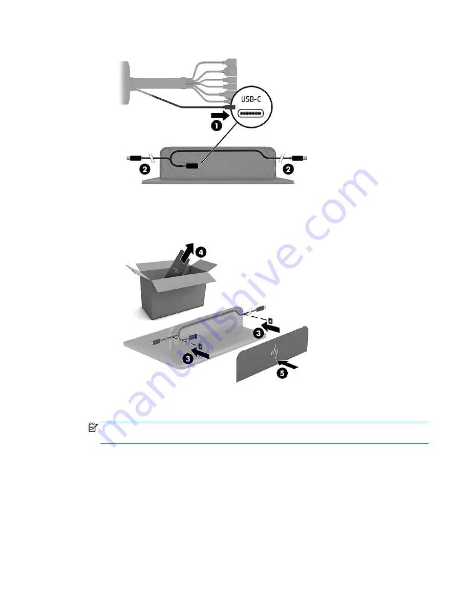
background image

b.

Insert a rubber plug at the cable exit point (3) to secure the cable.

c.

Remove the CoRC back cover from the shipping box (4) and attach it to the back of the CoRC (5).

6.

If the Wireless Display Module is installed, perform the following steps to install the wireless receiver 

transceiver:

NOTE:

The transceiver must face the front of the Wireless Display Module. For the best performance, 

be sure the line of sight between the transceiver and the Wireless Display Module is optimal.

a.

Connect a display power cord to an AC outlet (1).

b.

Use the included adhesive strip to secure the transceiver in place (2).

Setting up an Elite Slice G2 conferencing solution

15

Содержание Elite Slice for Meeting Rooms G2

Страница 1: ...Hardware Reference Guide HP Elite Slice for Meeting Rooms G2 ...

Страница 2: ...ument Part Number L14947 002 Product Notice This guide describes features that are common to most models Some features may not be available on your computer Software terms By installing copying downloading or otherwise using any software product preinstalled on this computer you agree to be bound by the terms of the HP End User License Agreement EULA If you do not accept these license terms your s...

Страница 3: ...jury IMPORTANT Indicates information considered important but not hazard related for example messages related to property damage A notice alerts the user that failure to follow a procedure exactly as described could result in loss of data or in damage to hardware or software Also contains essential information to explain a concept or to complete a task NOTE Contains additional information to empha...

Страница 4: ...iv About This Book ...

Страница 5: ...7 Connecting modules 7 Connecting modules 7 Connecting the optional Slice VESA Plate 8 Removing modules 10 Attaching the Elite Slice G2 to a mounting device 11 Installing a security cable 11 Connecting AC power 12 Setting up an Elite Slice G2 conferencing solution 13 Microsoft Skype Room System SRS conferencing solution 13 Intel Unite conferencing solution 18 3 Hardware upgrades 23 Serviceability ...

Страница 6: ... SSD 30 Appendix A Electrostatic discharge 32 Preventing electrostatic damage 32 Grounding methods 32 Appendix B Computer operating guidelines routine care and shipping preparation 33 Computer operating guidelines and routine care 33 Shipping preparation 34 Appendix C Accessibility 35 Supported assistive technologies 35 Contacting support 35 Index 36 vi ...

Страница 7: ...lice G2 features Bang Olufsen audio and wireless communication for Intel Unite or Microsoft Skype Room System SRS conferencing software Four speakers are on the Elite Slice G2 one in each corner and four microphones are on the top HP Elite Slice for Meeting Rooms G2 features 1 ...

Страница 8: ...mponent Item Component 1 Answer Call 4 Volume up 2 Mute 5 Reject Disconnect call 3 Volume down Rear components Item Component Item Component 1 Power button 5 USB ports 2 2 Power jack 6 Dual Mode DisplayPort D port 3 RJ 45 network jack 7 HDMI port 4 USB type C port with Alt Mode 8 Security cable slot 2 Chapter 1 Product features ...

Страница 9: ...hone Audio in microphone combo jack HP Video Ingest Module The Video Ingest Module is required for the Microsoft SRS This module enables a video source to be connected to the SRS The Video Ingest Module does not support Intel Unite software Item Component Item Component 1 Security cable slot 2 HDMI in port HP Video Ingest Module 3 ...

Страница 10: ...eiver in the room TIP For the best performance be sure the line of sight between the wireless receiver transceiver and the Wireless Display Module is optimal Item Component Item Component 1 Sync button 3 Security cable slot 2 Sync LED Item Component Item Component 1 HDMI port 5 VESA plate release button 2 USB Type A power connector 6 VESA plate light 3 Sync LED 7 Wireless receiver transceiver 4 Sy...

Страница 11: ...e total number of powered modules Item Component Item Component 1 Optical drive disc tray 3 Optical drive eject button 2 Optical drive light 4 Manual eject hole HP Slice VESA Plate optional The optional Slice VESA Plate enables the Elite Slice G2 assembly to be mounted onto a table The Elite Slide G2 should not be mounted to a wall or under a desk Item Component Item Component 1 Quick release latc...

Страница 12: ...umber laser etched on the base cover of the Elite Slice G2 A copy of these labels is inside the case Keep these numbers available for use when contacting support for assistance Item Component Item Component 1 Regulatory label 3 Module connector 2 Regulatory and service information 6 Chapter 1 Product features ...

Страница 13: ...modules turn off the Elite Slice G2 and disconnect it from any AC power source Modules cannot be hot plugged or hot swapped 1 Remove disengage the security cable if one is attached 2 Remove all removable media such as USB flash drives 3 Turn off the Elite Slice G2 properly through the operating system and then turn off any external devices 4 Disconnect the AC power cord from the Elite Slice G2 and...

Страница 14: ... Plate If the VESA Plate is connected the Elite Slice G2 can be mounted onto a table CAUTION Before connecting the VESA Plate turn off the Elite Slice G2 and disconnect it from any AC power source 1 Slide the quick release latch on the VESA Plate to the unlocked position Position the connected modules over the VESA Plate The VESA Plate does not have a module expansion connector Be sure that the po...

Страница 15: ...abs lock the VESA Plate to the Elite Slice G2 assembly If the VESA Plate is not correctly oriented the quick release latch cannot be moved to the locked position and the modules are not secured 4 Install a security cable in the VESA Plate security cable slot to prevent the quick release latch from being unlocked and the modules from being separated NOTE The security cable is designed to act as a d...

Страница 16: ... removable media such as USB flash drives 3 Turn off the Elite Slice G2 properly through the operating system and then turn off any external devices 4 Disconnect the AC power cord from the Elite Slice G2 and disconnect any external devices 5 If the VESA Plate is connected slide the quick release latch on the back of the VESA Plate to the unlocked position and lift the module stack off the VESA Pla...

Страница 17: ...ommends that you secure the Elite Slice G2 assembly by attaching a security cable to the rear of the VESA Plate This stops the quick release latch from being moved to the unlocked position and prevents accidental release of the modules The security cable is designed to act as a deterrent but it may not prevent the computer from being mishandled or stolen Installing a security cable The 10 mm ultra...

Страница 18: ...own 1 to expose the cable connectors b Pull the first and last connectors out 2 to each side c Beginning with the HDMI connector and finishing with the NIC connector plug all middle connectors into the rear ports 3 on the Elite Slice G2 d Connect side cables 4 e Push the port cover back over the cable connectors 5 to protect and secure the connectors 2 Connect remaining equipment such as a CoRC or...

Страница 19: ...pe Room System SRS conferencing solution The SRS ships with Microsoft SRS software HP Elite Slice G2 HP Center of Room Control CoRC HP Video Ingest Module and HP Cable and Port Cover The HP Wireless Display Module and HP VESA mount are optional Item Component Item Component 1 HP Elite Slice for Meeting Rooms G2 3 HP Cable and Port Cover 2 HP Center of Room Control CoRC 4 HP Video Ingest Module Set...

Страница 20: ...er to the Elite Slice G2 a Pull the port cover down 1 to expose the cable connectors b Pull the first and last connectors out to each side 2 c Beginning with the HDMI connector and finishing with the NIC connector plug all middle connectors into the rear ports 3 on the Elite Slice G2 d Connect the first and last connectors 4 e Push the port cover back over the cable connectors 5 to protect and sec...

Страница 21: ...ollowing steps to install the wireless receiver transceiver NOTE The transceiver must face the front of the Wireless Display Module For the best performance be sure the line of sight between the transceiver and the Wireless Display Module is optimal a Connect a display power cord to an AC outlet 1 b Use the included adhesive strip to secure the transceiver in place 2 Setting up an Elite Slice G2 c...

Страница 22: ...e Wireless Display Module and the wireless receiver transceiver are paired at the factory When the Elite Slice G2 is powered on the LEDs on the module and transceiver are solid white If they are not solid white press the Sync button on both module and transceiver The LEDs will flash white while they attempt to connect then become solid white when they connect If they do not connect check to be sur...

Страница 23: ...adapter to add the second HDMI port 8 Connect an optional USB camera to a USB A port on the Cable and Port Cover 9 Connect a local area network LAN to an RJ 45 network jack on the Cable and Port Cover 10 Connect the AC power cord to the power adapter 1 and the other end to an AC outlet 2 11 Connect the power supply connector to the power connector on the Cable and Port Cover 3 Setting up an Elite ...

Страница 24: ...nite conferencing system ships with Intel Unite software HP Elite Slice G2 and HP Cable and Port Cover The HP Wireless Display Module and HP VESA mount are optional Item Component Item Component 1 HP Elite Slice for Meeting Rooms G2 2 HP Cable and Port Cover TIP When routing cables under a table or other surface cable guides shown in red above should be used to minimize stress on the cables 18 Cha...

Страница 25: ...each side 2 c Beginning with the HDMI connector and finishing with the NIC connector plug all middle connectors into the rear ports 3 on the Elite Slice G2 d Connect the first and last connectors 4 e Push the port cover back over the cable connectors 5 to protect and secure the connectors 4 If the Wireless Display Module is installed perform the following steps a Connect a display power cord to an...

Страница 26: ...y 3 TIP For the best performance be sure the line of sight between the wireless receiver transceiver and the Wireless Display Module is optimal 5 To connect a display without the Wireless Display Module perform the following steps a Connect a display power cord to an AC outlet 1 20 Chapter 2 Setup ...

Страница 27: ... adapter to add the second HDMI port 6 Connect an optional USB camera to a USB A port on the Cable and Port Cover 7 Connect a local area network LAN to an RJ 45 network jack on the Cable and Port Cover 8 Connect the AC power cord to the power adapter 1 and the other end to an AC outlet 2 9 Connect the power supply connector to the power connector on the Cable and Port Cover 3 Setting up an Elite S...

Страница 28: ...10 Press the power button on the Elite Slice G2 11 Follow the Intel Unite instructions to install the conferencing software on the Elite Slice G2 22 Chapter 2 Setup ...

Страница 29: ...t safety feature Plug the AC power cord into a grounded earthed AC outlet that is easily accessible at all times To reduce the risk of serious injury read the Safety Comfort Guide It describes proper workstation setup and provides guidelines for posture and work habits that increase your comfort and decrease your risk of injury It also provides electrical and mechanical safety information This gui...

Страница 30: ...modules 1 Remove the Elite Slice G2 from any additional modules For instructions see Removing modules on page 10 2 Place the computer upside down on a flat surface covered with a soft cloth to protect the computer from scratches or other damage 3 Loosen the four captive screws securing the access panel and lift the panel off the computer 24 Chapter 3 Hardware upgrades ...

Страница 31: ...e connection port is clearly visible through the opening in the access panel 3 Tighten the four captive screws to secure the access panel to the computer 4 Reconnect any additional modules For instructions see Connecting or removing modules on page 7 Locating internal components Item Component Item Component 1 System memory modules 2 SSD Locating internal components 25 ...

Страница 32: ...following specifications industry standard 288 pins unbuffered non ECC PC4 17000 DDR4 2133 MHz compliant 1 2 volt DDR4 SDRAM SODIMMs Support CAS latency 15 DDR4 2400 MHz 15 15 15 timing Contain the mandatory Joint Electronic Device Engineering Council JEDEC specification The computer supports the following 512 Mbit 1 Gbit and 2 Gbit non ECC memory technologies Single sided and double sided SODIMMS...

Страница 33: ...e if only one memory module slot is populated The system operates in higher performing dual channel mode if the capacity of the memory modules in Channel A and Channel B are equal The system operates in flex mode if the capacity of the memory modules in Channel A and Channel B are not equal In flex mode the channel populated with the least amount of memory determines the total amount of memory tha...

Страница 34: ... Plated metal contacts to prevent corrosion and or oxidation resulting from having incompatible metals in contact with each other Static electricity can damage the electronic components of the computer or optional cards Before beginning these procedures ensure that you are discharged of static electricity by briefly touching a grounded metal object For more information see Electrostatic discharge ...

Страница 35: ...s lock it in place NOTE A memory module can be installed in only one way Match the notch on the module with the tab on the memory module slot 4 Replace the access panel For instructions see Replacing the access panel on page 25 The computer automatically recognizes the additional memory when you turn on the computer Upgrading system memory 29 ...

Страница 36: ...Removing the access panel on page 24 2 Remove the 4 screws 1 attaching the SSD cage to the system board and lift the cage 2 out of the chassis 3 Pull the tab 3 to disconnect the SSD power and data cable from the SSD 4 Remove the screws 1 securing the SSD in the cage and lift the SSD 2 out of the cage 5 Position the new SSD over the drive cage with the SSD connectors at the end with the thermal pat...

Страница 37: ... data cable 1 to the SSD 9 Set the drive cage 2 in the chassis Be sure that the SSD connectors are facing the back of the chassis 10 Align the drive cage tabs with the screw posts in the chassis and fasten the four screws 3 to secure the SSD 11 Replace the access panel For instructions see Replacing the access panel on page 25 Removing and replacing an SSD 31 ...

Страница 38: ...g methods Use one or more of the following methods when handling or installing electrostatic sensitive parts Use a wrist strap connected by a ground cord to a grounded workstation or computer chassis Wrist straps are flexible straps with a minimum of 1 megohm 10 percent resistance in the ground cords To provide proper ground wear the strap snug against the skin Use heelstraps toestraps or bootstra...

Страница 39: ...removed Do not stack computers on top of each other or place computers so near each other that they are subject to each other s recirculated or preheated air If the computer is to be operated within a separate enclosure intake and exhaust ventilation must be provided on the enclosure and the same operating guidelines listed above will still apply Keep liquids away from the computer and keyboard Ne...

Страница 40: ...f the computer and external devices 4 Disconnect the AC power cord from the AC outlet and then from the computer 5 Disconnect the system components and external devices from their power sources and then from the computer NOTE Ensure that all boards are seated properly and secured in the board slots before shipping the computer 6 Pack the system components and external devices in their original pac...

Страница 41: ...assistive features NOTE For additional information about a particular assistive technology product contact customer support for that product Contacting support We are constantly refining the accessibility of our products and services and welcome feedback from users If you have an issue with a product or would like to tell us about accessibility features that have helped you please contact us at 1 ...

Страница 42: ... 27 slots 26 specifications 26 Microsoft SRS conferencing 13 Microsoft SRS installing 18 module Cable and Port Cover 13 18 connecting 7 ODD Module 5 order 7 removing 10 sequence 7 Slice VESA Plate 5 Video Ingest 3 Wireless Display 4 mounting Elite Slice G2 11 O ODD Module 5 optical disc drive 5 P power 12 product ID location 6 R rear components 2 removing access panel 24 modules 10 SSD 30 replacin...

Страница 43: ...Wireless Display Module 4 wireless receiver transceiver 4 wireless receiver transceiver 4 Index 37 ...

Отзывы: